


Service Training
Section
2.6
Page
58
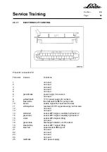
2.6.7
LTM CONTROL FOR WORKING HYDRAULIC SYSTEM AND STEERING
Electric fork trucks need hydraulic pumps driven by electric motors for the operation of hydraulic cylinders
for lifting, tilting, auxiliary hydraulics and steering. On series 336 trucks only one hydraulic pump is used for
the operation of the working hydraulic system and the power steering. The power requirement of the various
hydraulic cylinders and the attachments differs greatly. For example, a larger volume of oil is required for
the lifting than for tilting or operating the sideshift. If the working hydraulics pump is used for steering
purposes, only a low pump motor speed is needed. The speed control for steering is regulated by means
of a reed contact on the steering control valve and a speed sensor mounted on the left motor.
WHY AN LTM CONTROL IS USED FOR THE WORKING HYDRAULICS
To achieve a high degree of effectiveness of the hydraulic system, the pump should only deliver the amount
of oil that is actually needed for the work cycle in question. This requirement can be fulfilled by controlling
the speed of the pump motor with an LTM control as required by the hydraulic load.
The installation of an LTM control for the lift hydraulics brings measurable energy savings and, as a result,
a longer service life of the battery.
The amount of energy saved by the LTM control is essentially determined by the service conditions and by
the attachments fitted.
The largest energy saving is achieved with many work movements needing fine control over short driving
distances.
The LINDE LTM control has the following benefits for the user:
-
reduction of noise level
-
longer motor service life
-
longer lasting battery charge
-
longer battery service life
-
increased working safety
-
less motor brush wear
-
constant steering support
-
wear-free motor control
The electronic control unit has three separate inputs over which the motor speed can be controlled
independent of each other.
Summary of Contents for 336 Series
Page 2: ......
Page 8: ...ServiceTraining ...
Page 12: ...ServiceTraining Section 2 1 Page 4 ...
Page 14: ...ServiceTraining Section 2 1 Page 6 2 1 4 TRACTIONMOTORDISASSEMBLY ...
Page 19: ...ServiceTraining Section 2 2 Page 3 ...
Page 21: ...ServiceTraining Section 2 2 Page 5 ...
Page 27: ...ServiceTraining Section 2 2 Page 11 ...
Page 28: ...ServiceTraining Section 2 2 Page 12 ...
Page 33: ...ServiceTraining Section 2 4 Page 1 2 4 STEERING SYSTEM ...
Page 35: ...ServiceTraining Section 2 4 Page 3 ...
Page 37: ...ServiceTraining Section 2 4 Page 5 ...
Page 39: ...ServiceTraining Section 2 4 Page 7 ...
Page 41: ...ServiceTraining Section 2 4 Page 9 ...
Page 45: ...ServiceTraining Section 2 4 Page 13 ...
Page 47: ...ServiceTraining Section 2 4 Page 15 ...
Page 53: ...ServiceTraining Section 2 5 Page 5 ...
Page 54: ...ServiceTraining Section 2 5 Page 6 ...
Page 69: ...ServiceTraining Section 2 6 Page 15 ...
Page 74: ...ServiceTraining Section 2 6 Page 20 2 6 2 3 CIRCUIT BREAKER CONTACTOR 1K6 Circuit diagram ...
Page 94: ...ServiceTraining Section 2 6 Page 40 ...
Page 111: ...ServiceTraining Section 2 6 Page 57 Connector 1X6 1 15 V 2 Output signal 3 ...
Page 126: ...ServiceTraining Section 2 6 Page 72 2 6 9 2 LOCATION OF CONNECTORS FROM SERIES 7 95 ...
Page 128: ...ServiceTraining Section 2 6 Page 74 ...
Page 145: ...Section 2 6 Page 91 ...
Page 146: ......
Page 147: ......
Page 149: ...Section 2 6 Page 93 ...
Page 150: ......
Page 153: ...ServiceTraining Section 2 7 Page 3 ...
Page 157: ...ServiceTraining Section 2 7 Page 7 ...
Page 158: ...ServiceTraining Section 2 7 Page 8 ...
Page 163: ...Section 2 9 Page 5 ...
Page 164: ......
Page 166: ...ServiceTraining Section 2 10 Page 2 ...
Page 167: ......