


Service Training
Section
2.6
Page
49
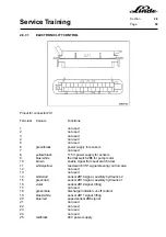
2.6.6.6.1
CHECKING THE MAXIMUM CURRENT AND HANDBRAKE CURRENT
Maximum current
- Jack up the truck and block it up safely.
- Connect current measuring pliers WM 120 to the cable from current sensor 1B3 to the directional
contactors.
- Fully depress the brake pedal and accelerator pedal.
NOTE:
The wheels must not turn.
- Read the current.
- The maximum current must be approx. 430 Ampere.
CAUTION: Perform the measurement quickly in order to prevent damage to the traction motors. The
maximum measuring time should not exceed 30 seconds.
Handbrake current
- Install the current measuring pliers as described above.
- Engage the handbrake and fully depress the accelerator pedal.
- Read the current.
- The handbrake current must be approx. 150 Ampere.
NOTE:
If the two current readings are not correct, the electronic traction control unit or the current sensor
must be replaced.
Summary of Contents for 336 Series
Page 2: ......
Page 8: ...ServiceTraining ...
Page 12: ...ServiceTraining Section 2 1 Page 4 ...
Page 14: ...ServiceTraining Section 2 1 Page 6 2 1 4 TRACTIONMOTORDISASSEMBLY ...
Page 19: ...ServiceTraining Section 2 2 Page 3 ...
Page 21: ...ServiceTraining Section 2 2 Page 5 ...
Page 27: ...ServiceTraining Section 2 2 Page 11 ...
Page 28: ...ServiceTraining Section 2 2 Page 12 ...
Page 33: ...ServiceTraining Section 2 4 Page 1 2 4 STEERING SYSTEM ...
Page 35: ...ServiceTraining Section 2 4 Page 3 ...
Page 37: ...ServiceTraining Section 2 4 Page 5 ...
Page 39: ...ServiceTraining Section 2 4 Page 7 ...
Page 41: ...ServiceTraining Section 2 4 Page 9 ...
Page 45: ...ServiceTraining Section 2 4 Page 13 ...
Page 47: ...ServiceTraining Section 2 4 Page 15 ...
Page 53: ...ServiceTraining Section 2 5 Page 5 ...
Page 54: ...ServiceTraining Section 2 5 Page 6 ...
Page 69: ...ServiceTraining Section 2 6 Page 15 ...
Page 74: ...ServiceTraining Section 2 6 Page 20 2 6 2 3 CIRCUIT BREAKER CONTACTOR 1K6 Circuit diagram ...
Page 94: ...ServiceTraining Section 2 6 Page 40 ...
Page 111: ...ServiceTraining Section 2 6 Page 57 Connector 1X6 1 15 V 2 Output signal 3 ...
Page 126: ...ServiceTraining Section 2 6 Page 72 2 6 9 2 LOCATION OF CONNECTORS FROM SERIES 7 95 ...
Page 128: ...ServiceTraining Section 2 6 Page 74 ...
Page 145: ...Section 2 6 Page 91 ...
Page 146: ......
Page 147: ......
Page 149: ...Section 2 6 Page 93 ...
Page 150: ......
Page 153: ...ServiceTraining Section 2 7 Page 3 ...
Page 157: ...ServiceTraining Section 2 7 Page 7 ...
Page 158: ...ServiceTraining Section 2 7 Page 8 ...
Page 163: ...Section 2 9 Page 5 ...
Page 164: ......
Page 166: ...ServiceTraining Section 2 10 Page 2 ...
Page 167: ......