background image

Torchmate 5100

24

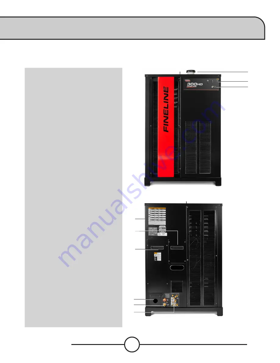
FineLine 170HD/300HD Overview 

Please refer to the complete operation and user manual for your FineLine located with the plasma unit. 

Press the power button on the face of the FIneLine to cycle the power. 


1

2

3

4

6

10

FRONT

1. 

LIFTING EYE

2. 

COOLENT FILL

3. 

STATUS LEDS

4. 

POWER ON/OFF BUTTON 


BACK

5. 

FILTER ACCESS PANEL (SIDE)

6. 

INPUT / OUPUT ACCESS PANEL

7. 

INPUT POWER ACCESS PANEL

8. 

POWER CORD STRAIN RELIEF

9. 

COOLENT HOSE CONNECTORS

10. 

GAS SUPPLY CONNECTORS

Controls 

»

8  

Summary of Contents for Torchmate 5100 Series

Page 1: ...March 31 2021 Copyright 2021 Lincoln Electric Cutting Systems USERGUIDE ...

Page 2: ...00 14 Water Table Operation 15 Filling the Watertable 16 Downdraft Operation 19 FlexCut 125 Plasma Controls Settings 20 FlexCut 200 Plasma Controls Settings 22 FineLine 170HD 300HD Controls Settings 24 Overview of the Visual Machine Designer 26 Using the Shape Library in VMD 38 Running a Job 40 Quality Test Cut 42 VMD Nest 44 5100 Bevel 47 Create a Bevel Cut 48 General Maintenance 58 Cut Quality 6...

Page 3: ... the shipment and contact Lincoln Electric Cutting Systems The plasma unit along with all of the connection cables will be secured to a separate pallet To remove the plasma power supply from the pallet team lift or forklift the plasma power supply and set aside until the machine is placed in its final operational location The plasma unit will sit on the floor near the cable carrier exit on the mon...

Page 4: ...e machine when installing the leveling feet Screw them halfway into the pads to get the most movement for leveling Once the machine is placed then level the table When the machine is level then follow the WATER FILL process Use ALL of the leveling feet to secure and level the table Make sure the table does not rock or have any movement once level The table is now ready to be filled with water if w...

Page 5: ... secure the arm in place Remove the bolts that are indicated in the drawing and reuse them to secure the arm 1 Remove the bolt from behind the monitor and two bolts on the swing bracket 2 Lift the monitor up and secure with the removed bolt 3 Grab the arm and swivel it 180 degrees into place 4 Re insert the bolts to secure the arm in place ...

Page 6: ...operations Any accessories will also be provided shop air by tapping into the two output 1 4 tubing push connects 120v Power Cord 15 NEMA 5 15P 1 4 O D Tubing Push Connect for accessories 1 4 Industrial Quick Disconnect to Plasma Cutter 1 4 Industrial Quick Disconnect Shop Air input Internally the 5100 comes pre wired and ready to run All systems are test fired and disconnected at the facility bef...

Page 7: ...t comply with the Standard for Attachment Plugs and Receptacles UL498 The product is considered acceptable for use only when an attachment plug as specified is properly attached to the supply cord GROUNDCONNECTION CONNECT GROUND LEAD PER LOCAL AND NATIONAL ELECTRIC CODE INPUTCORDSTRAINRELIEF ROUTE INPUT CORD THROUGH RELIEF AND TWIST NUT TO TIGHTEN POWERCONNECTIONBLOCK CONNECT EACH PHASE OF A THREE...

Page 8: ...rface 2 Remove the two 7 16 bolts and the locking bracket from the front mounting bracket 3 Lift the FlexCut 200 and place it on top and slightly forward of the FlexCool 35 4 Carefully guide the FlexCut 200 so that the quick lock feet on the bottom of the power source slide into the channels of the mounting brackets on top of the FlexCool 35 Be sure all 4 feet are within the channels 5 Slide the F...

Page 9: ...phase supply line A 1 75 inch 45 mm diameter access hold for the input supply is located on the case back Connect L1 L2 L3 and ground per connection diagrams and National Electric Code To access the input power connection block remove the seven screws and the left case side of the machine as shown COOLANT SUPPLY COOLANT RETURN TO FLEXSTART Input Cord Strain Relief Route input cord through relief a...

Page 10: ... Connect the ETHERNET connector to the back of the FlexCut 200 Attach the other end to the ETH1 port to the Fiber Optic box Attach the fiber optic and power cable to the converter box For full wiring instructions see the corresponding manuals for the FlexCut 200 and FlexCool 35 NOZZLE ARC LINK ELECTRODE WORK PLASMA GAS SHIELD GAS FROM CABLE CARRIER FROM CABLE CARRIER TO STAR GROUND Star Ground Sta...

Page 11: ...y covers must be securely installed Lift slowly not more than 8 in 203 2mm high to ensure even weight distribution Move slowly to prevent uncontrollable acceleration deceleration Unboxing and Leveling 1 Place the FineLine Power Supply on a flat and level surface 2 Remove the wooden crate and plastic bag surrounding the Power Supply 3 Remove the rear input cover to find the operator s manual and ac...

Page 12: ... issues Operational training is not included in phone technical support E mail Lincoln Electric will return e mail to the support torchmate com e mail address within 24 hours Monday Friday TorchmateTraining Lincoln Electric provides a number of training opportunities at our Reno Nevada campus Please call 775 673 2200 for details or visit http torchmate com training TorchmateAcademy Torchmate Acade...

Page 13: ... made from durable flame resistant material Disconnect the power source before performing any service or repairs When the power source is operating voltages in excess of 250 volts are produced This creates the potential for serious electrical shock possibly even fatal Insulate yourself from work and ground using dry insulation Wear dry gloves and clothing in good condition Take extra care when the...

Page 14: ...e a highly toxic gas and other irritating products Remove all sources of these vapors Gases used for plasma cutting and gouging can displace air and cause injury or death Always use enough ventilation especially in confined areas to ensure breathing air is safe Use an air supplied respirator if ventilation is not adequate to remove all fumes and gases Read and understand the manufacturer s instruc...

Page 15: ...en gas may be formed and trapped under aluminum work pieces when they are cut underwater or while using a water table DO NOT cut aluminum alloys underwater or on a water table unless the hydrogen gas can be eliminated or dissipated Trapped hydrogen gas that is ignited will cause an explosion Read and follow NFPA 51B Standard for Fire Prevention During Welding Cutting and Other Hot Work available f...

Page 16: ...ork cables If the torch cable is on your right side the work cable should also be on your right side Connect the work cable to the workpiece as close as possible to the area being cut or gouged Do not work next to cutting power source ARCRAYSCANBURN Plasma Arc Rays can injure your eyes and burn your skin The plasma arc process produces very bright ultraviolet and infrared rays which will damage yo...

Page 17: ...and marking operations create waste that can fragment and fly Make sure you and everyone close to the CNC machine during operations has proper eye protection PINCHANDCRUSHPOINTS Pinch and crush points are those normally moving parts of machinery like CNC machines that can pinch capture crush or sever parts of the body Be aware of hazardous pinch and crush points Never repair or adjust the machine ...

Page 18: ...MBUSTIBLES obtainable from American Welding Society 8669 NW 36 Street 130 Miami Florida 33166 6672 NFPA Standard 51 OXYGEN FUEL GAS SYSTEMS FOR WELDING CUTTING AND ALLIED PROCESSES obtainable from the National Fire Protection Association Batterymarch Park Quincy MA 02269 NFPA Standard 70 NATIONAL ELECTRICAL CODE obtainable from the National Fire Protection Association Batterymarch Park Quincy MA 0...

Page 19: ... hr or 1 750 m3 hr minimum Automatic Filter Cleaning Pressure Controlled Downdraft Configuration Multiple Zones Controlled By Motion Controller Safety Dual Channel Safety System Supporting Emergency Stop Switch Safety System Extended To External Peripherals External Drive Power On Switch Warranty 1 Year Warranty TORCHMATE5100CNC PLASMASYSTEMS FlexCut125 FlexCut200 FineLine170HD FineLine300HD PRODU...

Page 20: ...the Lincoln Electric CNC Cutting System provide sufficient space Three feet of work space 914 mm should be obstacle free around the machine Side load material opposite the cable carrier only Utilize the back of the machine to park the gantry while loading material A dedicated earth ground must be provided and should be installed in a manner to reduce trip hazard 113 25 167 Load From This Side Oper...

Page 21: ...NTAIN WORK AREA Lincoln Electric FineLine High Definition Power Supplies have a larger power box and a gas controller to mix several different types of gases utilized in HD plasma cutting The placement of these products with the 5100 must be within 6 of the cable chain s end This also determines the location of incoming power to the FineLine plasma cutter and the termination of gas leads to the pl...

Page 22: ...require a dedicated 3 8 I D hose for all inlet gas connections Quick connect fittings must not be used when connecting air to the FineLine power supply 120v Power Cord 15 NEMA 5 15P 1 4 O D Tubing Push Connect for accessories 1 4 Industrial Quick Disconnect to Plasma Cutter 1 4 Industrial Quick Disconnect Shop Air input Internally the 5100 comes pre wired and ready to run All systems are test fire...

Page 23: ...commended may result in nuisance shut offs from high inrush currents even if the machine is not being used at high currents Connection to the supply circuit can be by means of flexible supply cables or supply cables through conduit to a permanent installation The supply cables should have a 600 volt minimum rating and be sized according to local and national codes PowertoPlasma Voltage InputAmpers...

Page 24: ...round rod Ground rod installations are covered by National Electrical Code Consult with a qualified electrical technician to verify your system grounding Place the FlexCut plasma unit in the appropriate location Re install the torch lead and the work lead into the plasma power supply The FlexCut plasma unit is shipped with a work lead Ground Clamp attached to the star ground The FineLine plasma un...

Page 25: ... material being cut After repeated cutting generally after a year or so of normal cutting time you will need to replace the slats Perform the replacement when the slats can no longer support the material properly or if the build up is hindering the plate from being flat The center slat support is offset to create an ARC of slats This makes the slats less prone to getting damaged in straight cuts a...

Page 26: ...rier side of the gantry and one above the monitor 4 Press the GREEN BUTTON above the Operators Console This will power the motors 5 Press DATUM Machine will seek back left corner To power up your Torchmate 5100 CNC machine the following items need to be powered up Machine and Plasma Unit The machine will power the controller computer and touchscreen The switch is located on the rear of the machine...

Page 27: ...ou press RAISE WATER compressed air is pushed into the lower chamber This pushes the water up into the cutting table When you press LOWER WATER the ball valve will OPEN releasing the compressed air from the bottom chamber This allows the upper chamber to drain the water into the lower chamber To completely drain your table use the 2 QC ball valve in the FRONT LEFT of the table WaterCapacity Torchm...

Page 28: ...ll the table to allow proper operation Connect your air supply to the air inlet on the machine to proceed Step1 Step2 Press Log On Select Admin password 1234 Press OK Configuration wap will open Press the Water Fill tab If the Machine Settings window does not open in the upper left corner press MAIN MENU In the SELECT A PANEL window left click on CONFIGURATION wap Press OK and the Machine Settings...

Page 29: ...ns the external exhaust vent to allow the air to transfer out of the empty water tank while the water fills up Start to fill the table with water Once the internal tank fills past 2 in the tank the LOW WATER indicator will no longer display FillingtheWaterTable ...

Page 30: ...n chamber by pressing and holding the RAISE WATER button Once the water reaches the top of the slat release the RAISE WATER button If the water does not reach the top of the slats then directly add water to the table to get the water level to the top of the slats Now to control the water level function you will use the WATER LEVEL controls in the Plate Setup menu FillingtheWaterTable ...

Page 31: ...etween filter servicing OUTPUT ZONE 1 ZONE 2 ZONE 4 ZONE 3 OUTPUT ZONE 1 ZONE 2 ZONE 3 ZONE 4 Each zone is controlled by pneumatic actuators to open close the dampers inside the table to allow for proper air flow The zones will open close based on where the parts are established on the cutting bed and the plate origin If a part of a nest covers more than one zone then multiple zones will open to a...

Page 32: ...EDs on the Control Panel will light up FRONT 1 LCD DISPLAY 2 PRIMARY AIR GAS PRESSURE GAUGE AND REGULATOR KNOB 3 HOME BUTTON 4 ON OFF SWITCH 5 TORCH CONNECTION 6 WORK LEAD CONNECTION 7 MENU CONTROL KNOB BUTTON 8 PURGE BACK 9 AIR OR GAS INLET 1 4 IN NPT QUICK CONNECT 10 RECONNECT PANEL ACCESS 11 INPUT CORD STRAIN RELIEF 12 14 PIN CNC INTERFACE 13 FAN Controls 1 12 11 8 13 2 3 4 5 6 9 10 7 ...

Page 33: ...6 21 Bar 20 72 x 12 25 x 25 53 526 x 311 x 648 118 53 5 MECHANIZED CUT CAPACITY MATERIAL THICKNESS MILD STEEL Recommendedcutcapacityat32ipm 1in 25 4mm MAXIMUM CUT SPEEDS MILD STEEL 1 4in 6 35mm 180ipm 1 2in 12 7mm 72ipm 3 4in 19mm 40ipm 1in 25 4mm 23ipm PIERCE CAPACITY MATERIAL THICKNESS MILD STEEL Piercecapacitywithprogrammabletorchheightcontrol 3 4 in 19mm CONSUMABLES STARTER KIT FOR LC125M MACH...

Page 34: ...OME BUTTON 3 MENU CONTROL KNOB BUTTON 4 ON OFF SWITCH 5 SHIELD GAS OUTLET 6 NOZZLE LEAD CONNECTION 7 WORK LEAD CONNECTION 8 ELECTRODE LEAD CONNECTION 9 ARCLINK CONNECTOR 5 PIN 10 PLASMA GAS OUTLET 11 PURGE 12 SHIELD GAS REGULATOR 13 PLASMA GAS REGULATOR BACK 14 AIR OR GAS INLET 1 4 IN NPT QUICK CONNECT 15 115V 15A AUXILIARY POWER RECEPTACLE 16 15 AMP CIRCUIT BREAKER 17 ETHERNET CONNECTOR 18 10 AMP...

Page 35: ...n 12 7mm 72ipm 3 4in 19mm 40ipm 1in 25 4mm 23ipm PIERCE CAPACITY MATERIAL THICKNESS MILD STEEL Piercecapacitywithprogrammabletorchheightcontrol 3 4 in 19mm CONSUMABLES STARTER KIT FOR LC125M MACHINE TORCH BK244100 SK Removal Tool Nozzle BK277056 1 Qty Removal Tool Swirl Ring BK260105 1 Qty O Ring Lubricant BK716012 1 Qty Internal Retaining Cap 50 A BK244453 1 Qty Internal Retaining Cap 100 A BK244...

Page 36: ...sma unit Press the power button on the face of the FIneLine to cycle the power 1 2 3 4 6 10 7 5 FRONT 1 LIFTING EYE 2 COOLENT FILL 3 STATUS LEDS 4 POWER ON OFF BUTTON BACK 5 FILTER ACCESS PANEL SIDE 6 INPUT OUPUT ACCESS PANEL 7 INPUT POWER ACCESS PANEL 8 POWER CORD STRAIN RELIEF 9 COOLENT HOSE CONNECTORS 10 GAS SUPPLY CONNECTORS Controls 8 9 ...

Page 37: ...pm PIERCE CAPACITY MATERIAL THICKNESS MILD STEEL Piercecapacitywithprogrammabletorchheightcontrol 3 4 in 19mm CONSUMABLES STARTER KIT FOR FINELINE MACHINE TORCH BK602631 Removal Tool Electrode Socket BK602396 1 Qty Removal Tool Electrode Driver BK277086 1 Qty O Ring Lubricant 5 gram tube BK716012 2 Qty Retaining Cap 80 A BK602338 1 Qty Retaining Cap 140 A BK602339 1 Qty Retaining Cap 300 A BK60236...

Page 38: ...pens and controls all aspects of the file being entered or the creation of jobs Includes SHUTDOWN 2 View Screen Shows the Process Setup graphic of the job g code of the job graph of the AVHC lifter station movements and Oxy Fuel and Water Fill controls 3 Run Group These buttons control the start and stop of the job 4 Jogging Controls the torch movement on the machine along with program run speed 5...

Page 39: ...e VMD Nesting program See the Nesting section for an overview of the features Shape Library Feature opens the dialog to create a user defined shape based on 36 of the most common parts See the USING THE SHAPE LIBRARY section for details Plate Setup The options in Plate Setup allows you to make alterations to the job itself and control the water level on water table configurations ROW AND COLUMN Al...

Page 40: ...ator to control the level of water in the water table RAISE WATER When held down this will raise the water Release the button to stop raising the water LOWER WATER When held down this will lower the water Release the button to stop at the level required If the LOW WATER indicator is displayed the water level in the tank is low and will not raise the water past that level until the water level is s...

Page 41: ...default Standard user with a simplified interface TECH SUPPORT Used only for tech support password protected Shutdown SHUTDOWN will close the VMD and power down the computer This should be used when shutting down the system Prompts a dialog box to TURN OFF ACCUMOVE CONTROLLER Press the E Stop button to power down the controller The computer will then shut down Turn the power switch to OFF JobGroup...

Page 42: ...an be found in your FlexCut manual under Cut Charts Transfer Height Distance the torch will retract off the material to initiate a pilot arc prior to moving up to the pierce height Pierce Height Distance the head sits above the material during piercing Cut Height Distance between the torch tip and top of material during cutting Pierce Delay The time delay for the torch to pierce through the materi...

Page 43: ...s movement during operation Maximize Viewport Displays all views in one screen Graphics View The machine limits are displayed in blue The head is represented with white crossed lines Plasma assigned tool paths are displayed in red Plate Marker assigned tool paths are displayed in green Rapid travels will be a dashed grey line Zoom to Machine Zoom to the programmed machine limits Zoom to Job Zooms ...

Page 44: ...chine along with running jobs Active Run Dry Run Toggles between ACTIVE RUN and DRY RUN ACTIVE RUN Activates your torch to fire when you RUN a job DRY RUN Deactivates your torch from operation If in DRY RUN the torch will simulate all movements without firing the torch Run Job Run Job Starts the job that is loaded into the VMD Stop Stops any activity or motion of the machine Reset The resets the j...

Page 45: ... will move faster Continuous will move as long as your finger is active on the direction FEED RATE OVERRIDE Alter the running feedrate of the job that is active The feedrate updates the change on the next ARC ON command Incremental Jog Pressing a direction will travel the torch the assigned Incremental Distance Using the slider will give you increments between 000 100 Directly enter any number int...

Page 46: ...s User Defined Job runs off of the manually entered cut parameters Sample Voltage is a toggle between On or Off On with MODE AUTO At the beginning of the cut the controller learns the proper Arc Voltage and maintains the desired Cut Height value entered in the CUT PARAMETERS Off with MODE AUTO The AVHC will adjust based on the SET VOLTAGE and CURRENT VOLTAGE only If the SET VOLTAGE is different th...

Page 47: ...int Dashboard The dashboard displays the host indicators and tools for the operator Arc Voltage Displays the Arc Voltage feedback from the plasma during cutting Plasma Pierce Count Counts the ARC ON commands as they take place Reset clears the count back to zero Recommend to reset with changing of the consumables Process Displays the current cutting process Feedrate Displays the real time feedrate...

Page 48: ...r enabled How the Laser Works The laser is positioned at a slight angle to the torch so that it crosses directly under its centerline With the torch positioned properly on the machine and the material thickness entered into the system the z axis will make a position adjustment when activated so that the projected dot will land on the surface of the material underneath the centerline of the torch T...

Page 49: ...me required for the OXY cutting OFF Toggle to ON or OFF This will activate the PREHEAT DELAY time that is entered in the PREHEAT DELAY dialog EXTEND Toggles between EXTEND and CAPTURE When EXTEND is PRESSED this will extend the time until released It will then CAPTURE the time CONTINUE Active or not When pressed it will turn on the HIGH PRESSURE REGULATOR to start cutting Preheat Delay Input for t...

Page 50: ...Oxy Lead In Radius Creates a radius for your lead in If a line lead in is required then enter 0 Lead In The length of the pierce point movement into the tool path This is usually twice the kerf value of the set average Lead Out Length of the cut created out of the cut path If using plasma enter 0 Overburn Measured length past the end start point Used for thicker materials or in the oxy process Pre...

Page 51: ...S folder you will need to press BROWSE and locate your job IS JOB KERF COMPENSATED The SHAPE LIBRARY parts DO NOT accommodate for KERF compensation SELECT NO and it will add the kerf based on the material thickness to the part On VMDNest and TMCAD programmed jobs SELECT YES Once selected press OK The job will display in the GRAPHICS screen UsingtheShapeLibraryinVMD ...

Page 52: ...ing is clockwise 1 4 turn then press the DRIVE ENABLE green button to power the motors The machine can now be datumed Open a Job Once MACHINE ZERO has been established it is time to open a job and get it prepared to cut Press SELECT JOB and locate your file Set your Process In the PROCESS SETUP tab enter in the material thickness and amperage you are planning to cut This will populate the CUT PARA...

Page 53: ... screen toggle to DRY RUN Press RUN JOB This will simulate the job loaded without firing the plasma torch 5 If satisfied with the Dry Run and the machine movements toggle DRY RUN to ACTIVE RUN to cut the job loaded 6 Press RUN JOB If you find that the machine is moving too fast for the material you can alter the feedrate by using the FEEDRATE OVERRIDE slider bar By default the slider is set to 100...

Page 54: ... AUTO 7 Set the SAMPLE VOLTAGE to ON 8 Set the IHS ohmic detection to ON 9 Set the IHS MODE to ALWAYS 10 Set the Machine to Active Run If Dry Run is displayed press once to toggle to Active Run 11 Verify that the FEED RATE OVERRIDE is set to 100 When commissioning your new table it is recommened to cut the same quatity test cut included with the machine to validate similar output This quality chec...

Page 55: ...feature Z Axis moves toward the material touching the top of the material IHS ohmic detection Torch retracts to set PIERCE HEIGHT and will fire and starts the program Once the marking is complete the plasma will switch to cut all inside features first then move to the outside geometry Once cut is complete compare the cut to the provided sample and verify that they match This will provide proof tha...

Page 56: ...the tightest nest available for the size and thickness of material entered into the PROCESS STATIONS To properly process a job through the VMD Nest Start by entering the material in the PROCESS STATIONS tab The VMDNest program will use these parameters to assign the proper kerf and cut parameters to job Once all the parameters and consumables are established press NESTING The Nesting browse window...

Page 57: ...ter the dimentions of the plate being used This will establish the material limits for the nest Press SAVE ITEM LIST will open along with the NEST LAYOUT To add parts go to the right toolbar and press PARTS This will open the parts list Select IMPORT CAD DRAWINGS for DXF DWG files This will bring up the PART SELECTOR VMDNest ...

Page 58: ...at C ControllerData Jobs Checkboxes VERIFY Verify will display the layers assigned to the part ARTWORK Artwork will change the toolpaths to an ONLINE toolpath and bypass the kerf adjustments On the right is the JOBPROPERTIES that will be applied to your parts when posting IMPORTINGPROPERTIES holds basic changes to the POST and importing of the file TOOLINGPROPERTIES holds tool pathing configuratio...

Page 59: ...at are present and gives the part details In the LAYERS toggling the check boxes for the layers will display which portion of the drawing is assigned to which layer in the display If needing to change to a different process use the drop down list to assign that layer to the process By setting to IGNORE will drop out that layer from the toolpath process After validating at the bottom of the screen ...

Page 60: ...he nest size area In the parts list adds quantity displays nested unnested quantity and size of the part VMDNest Startthenest Once the quantities are entered select NESTING Then press NEST A prompt will ask ALL or SELECTED In the display will show the parts layed out in the material area assigned ...

Page 61: ...t Completethenest In the right toolbar select COMPLETE NEST OpenNestinVMD After pressing COMPLETE NEST the job will auto load into the VMD software In the AVHC tab set CUT PARAMETERS to PROGRAM DEFINED and process the job ...

Page 62: ...mited by consumables The bevel allows for a variety of complex cuts that can be produced on the 5100 with material thicker than 3 9 5 mm A C Z 45 45 BEVELKNIFEEDGE BEVELKNIFEEDGEWITHLAND BEVELK CUTNOLAND BEVELK CUTWITHLAND BEVELUNDERCUTKNIFEEDGE BEVELUNDERCUTWITHLAND Bevel Cuts Available Bevel Axis A Moves toward away from lifter station C Moves clockwise counter clockwise on lifter station Z Move...

Page 63: ...tware by double clicking the icon Once open a launcher will show all of the options that are available Select DRAW In the upper left corner select the FOLDER or go to FILE OPEN Once the WINDOWS BROWSE dialog opens change the FILE TYPE to DXF This will allow you to see only DXF files The software will open and DRAWING TYPES window will display Enter in a SHEET LENGTH and SHEET WIDTH This measuremen...

Page 64: ...et up for the cut file navigate to the bottom of the layout and select EDIT MACHINE Select EDIT MATERIAL The MATERIAL window will display Locate the thickness of material planning to be cut SELECT it and press OK Once the MACHINE SELECTION window opens select the FLEXCUT 200 or other power supply oxy Press OK CreateaBevelCut ...

Page 65: ... multiple amperages CUT GAS can be altered based on the material and amperage being used Press SAVE The job will now display in the DRAW program Left click on SELECT OBJECT in the top tool bar Left click on the lines to create the BEVEL Each line will show dotted when selected On the right side of the screen will display the BEVEL tool path toolbar Select the bevel type you wish to apply to the jo...

Page 66: ... be entered for each type of cut Cuts with Lands will process two cuts per bevel to accommodate the land portion 1 Knife Edge 2 Undercut 3 Knife with Land 4 Undercut with Land 5 K Cut with Land After entering the parameters for the bevel press OK 1 Knife Edge 2 Undercut 3 Knife Edge with Land 4 Undercut with Land 5 K Cut with Land CreateaBevelCut ...

Page 67: ...n the bevel type To apply the tool path to the job after all the bevels have been entered press the APPLY PATH function This will APPLY the appropriate tool path for your cut The drawing is blue and the tool path will be red BEVEL cuts will generate a LOOP to allow the torch body to maneuver into the appropriate position for the bevel cut CreateaBevelCut ...

Page 68: ...ve your file by going to FILE SAVE When the dialog comes up to SAVE THE NESTED SHEET press YES Now go to FILE EXIT In the QuickCAM Bevel dialog select ORDER PROCESSING In the ORDER PROCESSING window press ADD JOB The ADD JOB window will appear CreateaBevelCut ...

Page 69: ...57 User Guide Enter a name into JOB NAME If METRIC is required check METRIC Press SAVE The EDIT JOB GROUP window will populate Press SAVE To add the part to the NEST press ADD ITEM CreateaBevelCut ...

Page 70: ... tool path to the job in the lower left In the ITEM LIST changing the QUANTITY will allow for irregular part nesting based on the sheet size entered Press NEST SETTINGS at the top of the screen This will open the NEST properties In the upper left verify that the POST is set to your Plasma power supply At the bottom of the NEST SETTINGS verify the AMPS and AIR CreteaBevelCut ...

Page 71: ...splay your nest along with the part in the display Press POST PROCESS Press NEST SETTINGS at the top of the screen This will open the NEST properties In the upper right verify that the POST is set to your plasma power supply At the bottom of the Nest Settings verify the AMPS and AIR for the POST to write the CUT SETTINGS for your part Press NEST ...

Page 72: ...he PATH to C CONTROLLER DATA JOBS To save to a Flash Drive or another drive press the three dots and open the BROWSE dialog Your FILE will be named numerically based on the NESTED PLATES SHEET NAME In this example the cut file would be named 0000200001 GM In the TOP tool bar area press CLOSE JOB The file can then be brought into VMD for cutting The NESTED JOB MANAGER will display Press the X in th...

Page 73: ...he FlexCut and FineLine plasma power supplies see their Owners Manual Thenozzle is the most frequently replaced consumable A sign the nozzle needs to be changed is an excessive amount of both dross and bevel angle appearing in your cuts On the nozzle itself you ll find that a larger orifice or an irregularly shaped hole will be the telltale signs of excessive wear Theshieldcap hold it up to a ligh...

Page 74: ...eration of the cassettes that can cause issues for the gantry to move properly on the linear rails LECS recommends Mobil SHC Mobilith SHC 100 lithium based grease This product can be sourced and purchased locally Load the grease cartridge into a grease gun and grease each zerk The arrows indicate all the zerks that need to be greased Side Linear Rail Y Axis Zerk Torch Carriage Linear Rail X Axis Z...

Page 75: ...eping the machines performance optimal and extending the life of the gear rack The cartridges need to be turned on and set to the appropriate setting for your application At the factory these oilers will have their application tubes primed and will pressurize the system to start applying the oil to the felt rollers There are 3 lubricators installed on the 5100 One on each end of the gantry under t...

Page 76: ... indicator will illuminate the position the dip switches are set to and will blink every 20 seconds We recommend setting the dip switches to 4 ON until the machine use is determined This setting states that the lubricator will apply oil to the felt wiper for 6 months and the cartridge will need to be replaced Use this chart to help determine the proper setting for your application If you notice po...

Page 77: ...he best bevel is achieved by using a climbing cut The best bevel is to the right of the direction of travel Corners can have more bevel than a normal cut This is caused when the machine slows down for the direction change A lower amperage in some cases allows for slower travel speeds and reduces slowdown bevel through corners Sharp corners can be achieved by cutting a larger shape that puts the sl...

Page 78: ...rch height Torch too low Equal bevel on all sides Minimal bevel Longest consumable life Unequal bevel One side may be straight the another excessively beveled Can be caused by worn tip Excessive bevel Cut may not go all the way through material Reversed bevel Torch may contact material and short out or damage tip Position of torch while cutting Bevel of finished part ...

Page 79: ...on contacting the material causing the cut to not fully penetrate the material When the machine begins to move before a pierce is completed the cut will not complete In this case the dwell time or pierce delay must be adjusted to allow for enough time to pierce the material When a cut s path does not return to the starting point there may be mechanical slipping or binding In some cases it will be ...

Page 80: ...g to the thickness of the material and amperage you are running Load the LINE SPEED TEST gm file Enter in the AVHC settings according to the cut chart Jog the head to the bottom left corner SET PLATE ORIGIN Run the LINE SPEED TEST Once the test is complete there are a few things to look for On the top of the cut you want to see a clean cut without a lot of bevel Ideally it has the same kerf width ...

Page 81: ...69 User Guide Use this template to create your own custom cut charts using the line speed test Material Thickness Type Amperage Cut Speed Pierce Delay Pierce Height Cut Height Build Your Own Cut Chart ...

Page 82: ...s W or V check Fuse 2 in the electrical cabinet When the machine is turned on the computer and monitor do not power on Check power at the supply side Verify breakers and any GFCI outlets Check Fuse 4 in the electrical cabinet The water level does not adjust when clicking the Up Down button on the main screen Restore Shop Air to the tables manifold None of the downdraft doors operate during a cut R...

Page 83: ...is Oblong holes Remove X cover and evaluate belt condition Loosen the motor bolts and tighten tension screw to proper tension Tighten motor bolts LaserFaults Problem Solution An error message occurs when attempting to turn the Laser on stating The laser cannot be activated in Active Run Toggle the system to Dry Run mode The laser does not appear to be landing where the centerline of the torch woul...

Page 84: ......

Page 85: ......

Page 86: ......

Page 87: ...tion Accordingly Lincoln Electric does not warrant or guarantee or assume any liability with respect to such information or communications Moreover the provision of such information or technical information does not create expand or alter any warranty on our products Any express or implied warranty that might arise from the information or technical information including any implied warranty of mer...

Reviews: