MODBUS Register Map v1.49
248083401-1 Rev 5
A-13
Data and
Alarm
Registers
Data and Alarm Enable Registers
The Data and Alarm Enable input registers (43xxx series) are read/
write. All enable data items are 4 bytes long and are stored across 2
registers. Byte and word ordering is big-endian. Thus, data items are
formed by placing the high bytes in front of the low bytes. For
example:
<High Bytes><Low Bytes> = <4 Byte Data Item>
The 43xxx register series is used to determine which particle data
channel is ENABLED and which are set to ALARM ENABLE. These
registers supersede the older Data Enable Registers (31xxx) which
have been obsoleted.
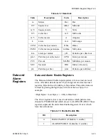
m
Meters
Bar
Bar
ft^2
Square feet
mBar
Milli-bar
m^2
Square meters
V
Volts
ft^3
Cubic feet
mV
Milli-volts
m^3
Cubic meters
A
Amperes
L
Liters
mA
Milli-amps
CFM
Cubic feet per minute
Ohm
Ohms
CMM
Cubic meters per minute
mOhm
Milli-ohm
L/m
Liters per minute
p/f3
Particles per cubic foot
p/m3
Particles per cubic meter
LPM
Liters per minute
PCT
Percent
MLPM
Milliliters per minute
SEC
Seconds
IHG
Inches of mercury
p/L
Particles per liter
p/ml
Particles per milliliter
Table A-12 Data Units
Units
Description
Units
Description
Table A-13 Enable/Disable Bits
Bit
Description
0
DATA ENABLE (0=disable; 1=enable)
1
ALARM ENABLE (0=disable; 1=enable)
Summary of Contents for REMOTE Active Count
Page 1: ......
Page 2: ...00...
Page 6: ......
Page 10: ...Lighthouse REMOTE Active Count Installation Guide ii 248083401 1 Rev 5...
Page 12: ...Lighthouse REMOTE Active Count Operating Manual 1 2 248083401 1 Rev 5...
Page 56: ...MODBUS Register Map v1 49 248083401 1 Rev 5 A 18...
Page 58: ...Lighthouse REMOTE Active Count Installation Guide B 2 248083401 1 Rev 5...
Page 61: ...00...
Page 62: ......


