Lighthouse REMOTE Active Count Operating Manual
A-10
248083401-1 Rev 5
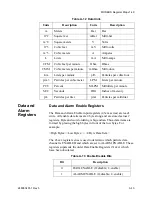
Data Status Byte (30007 - 30008)
Note:
Although
MODBUS sends 4 bytes
of status information,
Lighthouse instruments
only use the first (least
significant) byte.
The registers used for the Data Status Byte are 30007 and 30008.
The bit order of the Data Status Byte is 7 to 0, where bit 7 is the most
significant bit and bit 0 is the least significant bit.
The bits within the Data Status Byte are flagged to indicate particular
conditions of the currently indexed data record.
If multiple states occur, the bits are added together. For example, a
Flow Alert and a Particle Overflow would return a value of 6 in register
30008 (bits 1 and 2 are set TRUE).
Bits 7 to 31 are currently unused.
Valid Data in Channels (30074)
Register 30074 represents the flag bits corresponding to valid data
present in the particle register range.
Alarm Flags in Channels (30076)
Register 30076 represents the flag bits corresponding to particle
Table A-9 Data Status Byte
Bit
Description
0
Laser Alert Status
0 = Laser is OK 1 = Laser Alert
1
Flow Alert Status
0 = Flow Rate is OK 1 = Flow Rate Alert
2
Particle Overflow Status
0 = No overflow 1 = Overflow occurred
3
Instrument Service Status
0 = Working correctly 1 = Malfunction detected.
4
Threshold High Status
0 = Threshold not exceeded 1 = Threshold exceeded
5
Threshold Low Status
0 = Threshold not exceeded 1 = Threshold exceeded
6
Instrument Sampler Status
0 = Nominal Operation 1 = Sampler Error
Summary of Contents for REMOTE Active Count
Page 1: ......
Page 2: ...00...
Page 6: ......
Page 10: ...Lighthouse REMOTE Active Count Installation Guide ii 248083401 1 Rev 5...
Page 12: ...Lighthouse REMOTE Active Count Operating Manual 1 2 248083401 1 Rev 5...
Page 56: ...MODBUS Register Map v1 49 248083401 1 Rev 5 A 18...
Page 58: ...Lighthouse REMOTE Active Count Installation Guide B 2 248083401 1 Rev 5...
Page 61: ...00...
Page 62: ......

