Lighthouse REMOTE Active Count Operating Manual
A-8
248083401-1 Rev 5
Data
Registers
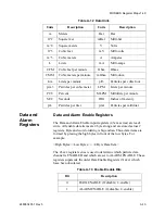
Data is stored in the input registers (30xxx series), which are read-only.
All data items are four bytes long and are stored across two registers.
Byte and word order for integer data is big-endian. Thus, data items are
formed by placing the high bytes in front of the low bytes.
Example:
<High Bytes><Low Bytes> = <4 Byte Data Item>
IEEE floating point has big-endian byte order and little-endian word
order. Thus, analog data items are formed by placing the low bytes in
front of the high bytes.
Example:
<Low Bytes><High Bytes> = <4 Byte Data Item>
Not all particle and analog channels are necessarily active. Retrieving
data from an inactive channel returns garbage. See the Data Enable
Registers section of this document for details on how to record data
from active channels.
This entire series of registers represents one data record in the device.
The Record Index Register (40025) must be changed to index other
records here.
The first record in the data buffer is located at Index=0. The most
recently saved value is at Index=-1.
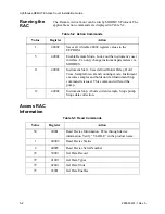
1152
Changes instrument baud rate to 115200K upon command
execution.
Table A-7 Command Register
Value
Action
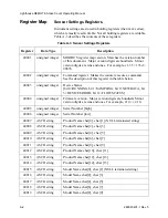
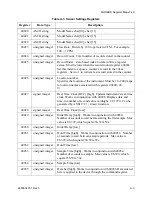
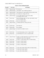
Table A-8 Data Registers
Register
Data Type
Description
30001
signed integer
Timestamp [high] (# of seconds
since midnight, 1/1/1970)
30002
signed integer
Timestamp [low]
30003
unsigned integer
Sample Time [high] (In seconds)
30004
unsigned integer
Sample Time [low]
Summary of Contents for REMOTE Active Count
Page 1: ......
Page 2: ...00...
Page 6: ......
Page 10: ...Lighthouse REMOTE Active Count Installation Guide ii 248083401 1 Rev 5...
Page 12: ...Lighthouse REMOTE Active Count Operating Manual 1 2 248083401 1 Rev 5...
Page 56: ...MODBUS Register Map v1 49 248083401 1 Rev 5 A 18...
Page 58: ...Lighthouse REMOTE Active Count Installation Guide B 2 248083401 1 Rev 5...
Page 61: ...00...
Page 62: ......


