Page
|
9
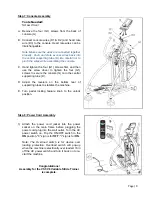
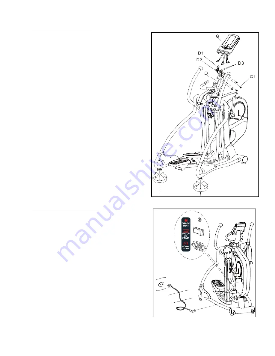
Step 7: Console Assembly
Tools Needed:
Screw driver
A. Remove the four (G1) screws from the back of
console (G).
B. Connect console wires (D1 & D2) and heart rate
wire (D3) to the console. Heart rate wires can be
interchangeable.
Note: Make sure the wires are connected together
properly. Push and store excess wires back into
the central supporting tube (D). Be careful not to
pinch the wires while assembling the console
.
C. Hand tighten the four (G1) screws first, and then
use the screw driver to tighten the four (G1)
screws to secure the console (G) onto the central
supporting tube (D).
D. Adjust the levelers on the bottom rear of
supporting tubes to stabilize the machine.
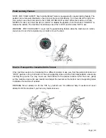
E. Turn pedal locking feature knob to the unlock
position.
Step 8: Power Cord Assembly
1) Attach the power cord jacket into the power
socket on the main frame before plugging the
power cord plug into the wall outlet. Turn the AC
power switch on. Flip the ON/OFF switch to the
ON
position. "0" sign is for
OFF
; "I" sign is for
ON
.
Note: The Overload switch is for device over
loading protection. Overload switch will pop-up
when the machine is electrically over loaded. Turn
off the AC power switch and turn it back on to re-
start the machine.
Congratulations!
Assembly for the VST-V8 Variable Stride Trainer
is complete.
Summary of Contents for VST-V8
Page 1: ...User s Product Manual LifeCORE VST V8 Variable Stride Trainer...
Page 6: ...Page 5...
Page 25: ...Page 24...
Page 26: ...Page 25...


