Page
|
6
Step 1: (R) Side Supporting Tube Assembly
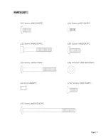
Note: Use page 5 as a reference to help
distinguish correct bolts for assembly, also add
the supplied blue loctite in the owner’s manual
bag to the threads of each user installed
hardware for added support.
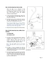
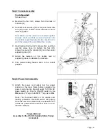
A. Locate (F2) (R) side supporting tube; remove the
two preassembled (J1) screws M8X16 from the
top of the receiver tube.
B. Assemble (C2) (R) side connecting tube onto (F2)
(R) side supporting tube, use the previously
removed (J1) screws M8X16 to join them.
Note: Only hand tighten the (J1) screws M8X16
until assembly is fully completed in step 2. Lay
arms down on the ground for easier assembly.
Adjust receiver tube to help align holes.
C. Repeat the same two steps for left side assembly.
Step 2: (R) Side Supporting Tube and Main Frame
Assembly
Tools Needed:
5mm Allen wrench
6mm Allen wrench
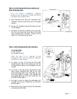
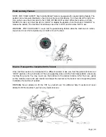
A. As shown in Views A & B) Assemble the right side
supporting tube assembly (C2 & F2) to the
machine. Slide the lower portion (F2) to the
bottom of main frame (A) first. Use two (J2)
screws M8x55 to join the tube to the frame.
Note: Only hand tighten the two (J2)
screws
M8x55
until instructed to use the tool to finish
assembly.
B. As shown in View A) Assemble the right top
supporting tube assembly (C2 & F2) onto the
upper main frame (A). Use one (J8) screw M8x20
to join the tube to the frame.
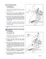
C. Now that the right side supporting tube assembly
is complete, tighten all screws from steps 1 & 2 as
show in View A one (J8), View B two (J2) & View
C four J1 screws. Use the 5mm & 6mm Allan
wrench to fasten bolts firm.
Summary of Contents for VST-V8
Page 1: ...User s Product Manual LifeCORE VST V8 Variable Stride Trainer...
Page 6: ...Page 5...
Page 25: ...Page 24...
Page 26: ...Page 25...


