6
The
Nfinity
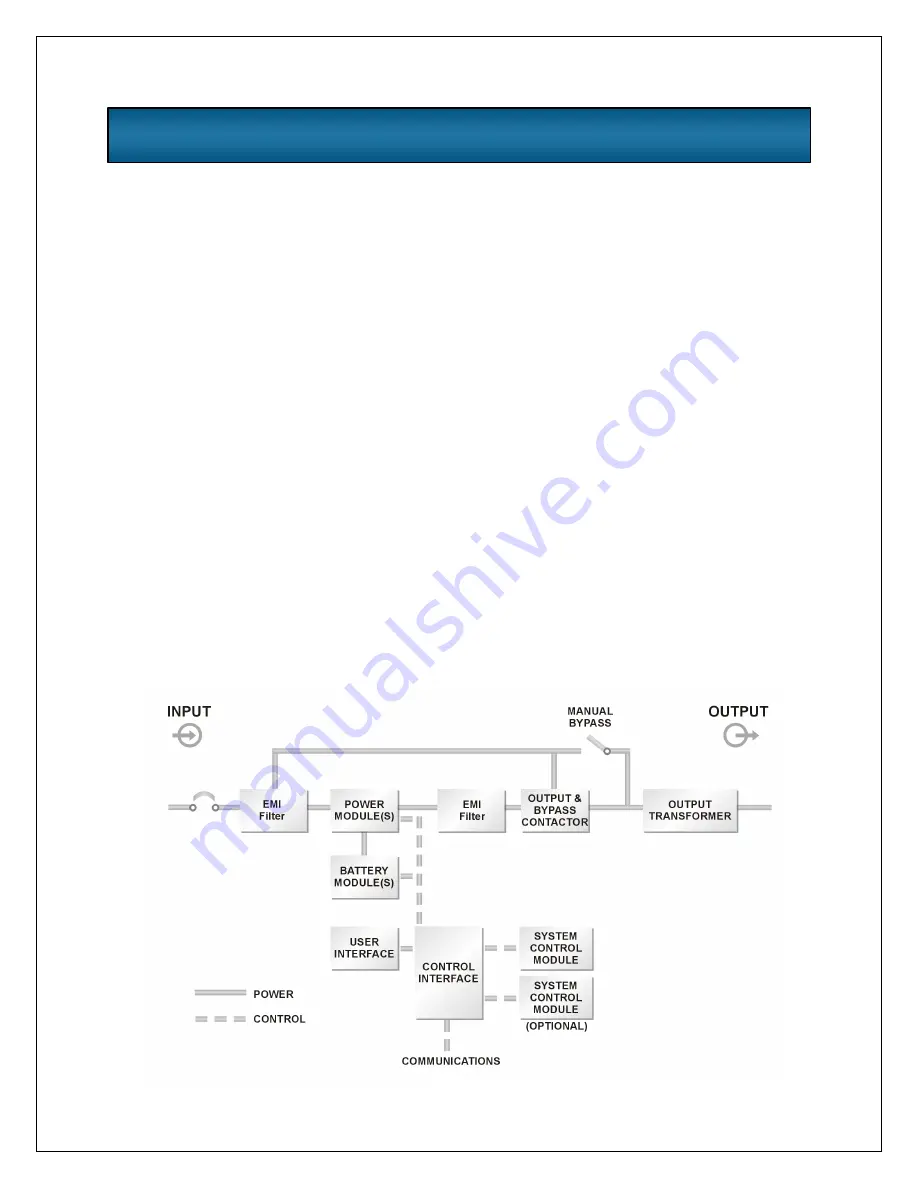
UPS is designed to operate as a true
on-line system in the following modes:
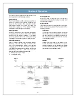
Normal Mode
The Power Module rectifiers derive power from a
utility AC source and supplies regulated DC
power to the inverter. The module’s inverter
regenerates precise AC power to supply the
connected equipment. The battery charger
maintains a float-charge on the battery.
Back-Up Mode
When AC utility fails, the connected equipment
is supplied power by the inverter, which obtains
energy from the battery modules. The output
power equipment will not be interrupted during
the failure or restoration of the AC utility source.
Auto Restart Mode
After a power outage and complete battery
discharge, once the AC utility is restored, the
UPS will automatically restart and resume
supplying power to the connected equipment.
This feature is enabled at the factory, but can be
disabled by the user. The user can also
program two auto restart delay settings:
1. Battery capacity level (%)
2. Countdown timer
Recharge Mode
When AC utility is restored, the unit will then
automatically recharge the battery modules until
they are fully charged.
Bypass Mode
The bypass provides an alternate path for power
to the connected equipment that operates in the
following manner:
Automatic
In the event of an internal failure or should
the inverter overload capacity be exceeded,
the UPS performs an automatic transfer of
the connected equipment from the inverter
to the bypass source.
Manual
Should the UPS need to be taken out of
service for limited maintenance or repair,
manual activation of the bypass will cause
an immediate transfer of the equipment from
the inverter to the bypass source.
Modes of Operation
Summary of Contents for 12 bay
Page 1: ...User Manual English 208 V 240 V 60Hz 4 to 16 kVA Power System...
Page 2: ......
Page 4: ...2 Glossary of Symbols...
Page 5: ...3 Introduction General Description Modes of Operation Major Components...
Page 7: ...5...
Page 12: ...10 Installation Preparation Unloading Cable Installation Communications...
Page 20: ...18 Operating Instructions Controls and Indicators Operating Procedures Main Menu...
Page 33: ...31 Troubleshooting Alarm Messages Module LED Indication Module Replacement...
Page 38: ...36 Maintenance Proper Care Scheduled Maintenance Replacing Fan Filters...
Page 40: ...38 Reference Specifications Battery Run Times Warranty Technical Support...


