16
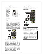
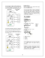
Connecting to External Panel Boards
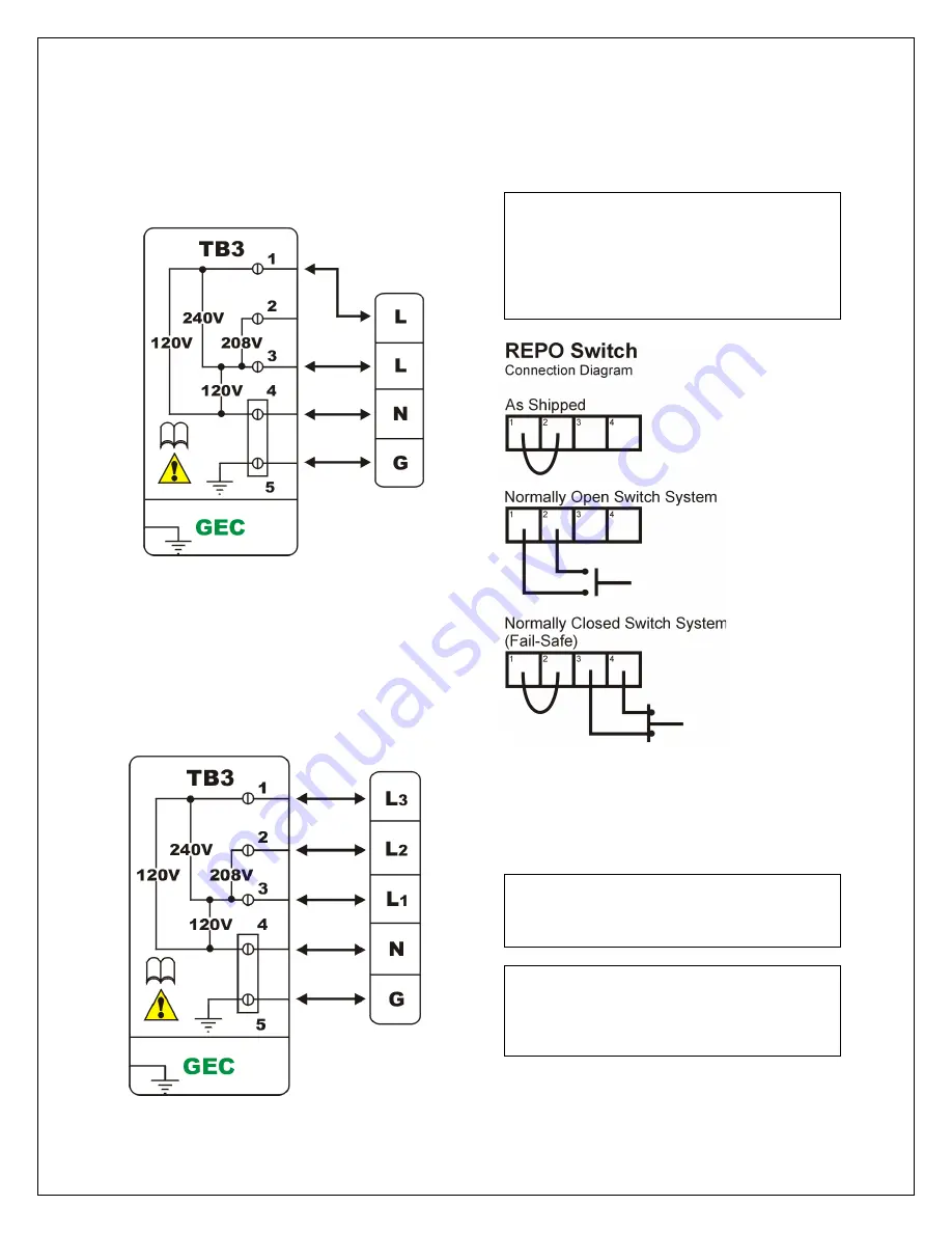
If connected equipment will operate at 240 / 120
VAC, use a standard single-phase panel board.
If connected equipment will ONLY operate at
208 / 120 VAC, use a three-phase panel board.
Ensure that all 120V equipment is connected
L
1 –
N
,
L
3
– N
.
Ensure that all 208V equipment is
connected L
1
– L
2.
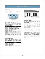
REPO Switch
Nfinity
is equipped with a Remote Emergency
Power Off (REPO) Switch.
The user must supply a means of interfacing
with the REPO circuit to allow disconnecting
the UPS input feeder breaker to remove all
sources of power to the UPS and connected
equipment to comply with national and local
wiring codes / regulations.
Remove
jumper
before
wiring.
1 = 24V DC, 35 mA
2 = sense
3 = sense
4 = ground
If the installation does not require connection
to a REPO system, the jumper must be
removed.
Caution:
To maintain safety (SELV) barriers
and electromagnetic compatibility signal
cables should be segregated and run
separately from power cables.
UPS Output
Panel Board
Input
UPS Output
Panel Board
Input
Summary of Contents for 12 bay
Page 1: ...User Manual English 208 V 240 V 60Hz 4 to 16 kVA Power System...
Page 2: ......
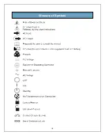
Page 4: ...2 Glossary of Symbols...
Page 5: ...3 Introduction General Description Modes of Operation Major Components...
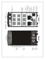
Page 7: ...5...
Page 12: ...10 Installation Preparation Unloading Cable Installation Communications...
Page 20: ...18 Operating Instructions Controls and Indicators Operating Procedures Main Menu...
Page 33: ...31 Troubleshooting Alarm Messages Module LED Indication Module Replacement...
Page 38: ...36 Maintenance Proper Care Scheduled Maintenance Replacing Fan Filters...
Page 40: ...38 Reference Specifications Battery Run Times Warranty Technical Support...

