29
Event Log
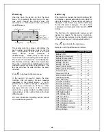
One may open the Event Log from the main
menu. By accessing the Event Log, the user
may scroll through the
Nfinity’
s past 255
occurrences in chronological order by pressing
the
$
#
buttons.
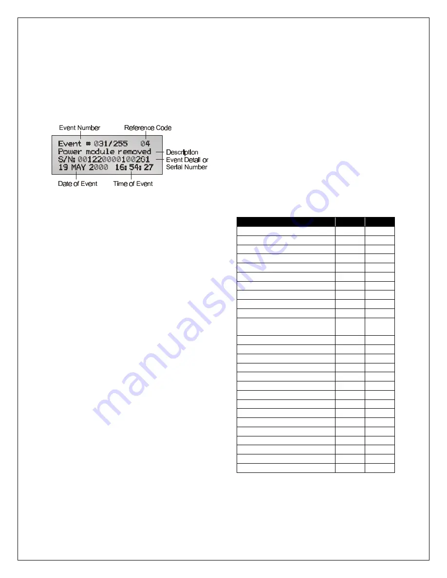
The typical event log screen will display the
event number and reference code on the first
line. The purpose of this code is to assist
factory trained service personnel in
troubleshooting. Please make a note of the
code number when contacting technical support.
The second line contains the event description.
The third line will have either more detail about
the event, a serial number indicating as to which
module the event occurred, or be left blank. The
last line will show the date and time the event
occurred.
Press
"
to go back to the main menu.
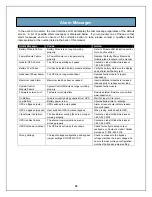
In the event of an event / alarm, the User
Interface LCD will display the last message
regardless of the default screen. A list of
possible event / alarm messages is displayed at
right. If you encounter one of these or other
messages and are unsure of the corrective
action to take, please contact a qualified Liebert
representative at the number listed in the back
of this manual.
For more information regarding events, consult
the troubleshooting section.
Alarm Log
When an alarm sounds, the User Interface LCD
will display a general explanation as to what the
alarm is indicating. These alarms will also be
displayed in the Alarm Log, which will display
the last 32 alarm messages. To view these
messages in chronological order, press the
$
#
buttons.
The first line of a typical alarm log screen will
display the reason for the alarm occurrence.
The second line will give a more specific detail
of the occurrence (i.e.; module serial number).
Press
"
to go back to the main menu.
Below is a list of possible events / alarms.
Occurrence
Event Alarm
Battery EOD
4
Battery Mod Removed
4
Battery Module Added
4
Battery Module Fail
4
4
Battery Test Fail
4
4
Battery Test Pass
4
Display Panel Added
4
Display Panel Removed
4
Firmware Error
4
4
General UPS Fail
4
4
Main Control Fail with
redundant control
4
4
Max Load Alarm
4
4
Power Mod Added
4
Power Mod Failure
4
4
Power Mod Removed
4
Red. Power Alarm
4
4
Transformer Fan Fail
4
4
UPS Auto Restart
4
UPS CANBus Fail
4
4
UPS Low Battery
4
4
UPS on Battery
4
4
UPS on Bypass (auto)
4
4
UPS on Bypass (manual)
4
4
UPS Shutdown
4
UPS Shutdown Imminent
4
Wrong Voltage
4
4
Summary of Contents for 12 bay
Page 1: ...User Manual English 208 V 240 V 60Hz 4 to 16 kVA Power System...
Page 2: ......
Page 4: ...2 Glossary of Symbols...
Page 5: ...3 Introduction General Description Modes of Operation Major Components...
Page 7: ...5...
Page 12: ...10 Installation Preparation Unloading Cable Installation Communications...
Page 20: ...18 Operating Instructions Controls and Indicators Operating Procedures Main Menu...
Page 33: ...31 Troubleshooting Alarm Messages Module LED Indication Module Replacement...
Page 38: ...36 Maintenance Proper Care Scheduled Maintenance Replacing Fan Filters...
Page 40: ...38 Reference Specifications Battery Run Times Warranty Technical Support...

