8
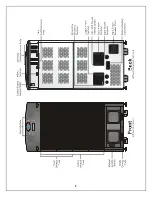
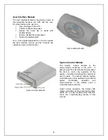
User Interface Module
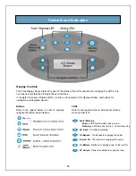
The User Interface Module is the primary source of
communication between the UPS and the user.
From the interface, the user can:
§
View the status of the UPS
§
Custom configure the system
§
Review the event log to assist with
troubleshooting
§
Enable / disable the output power
§
Silence the audible alarm
For a more detailed explanation on how to operate
the User Interface module, see the Controls and
Indicators section of this manual.
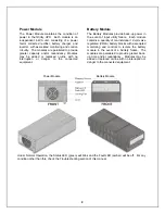
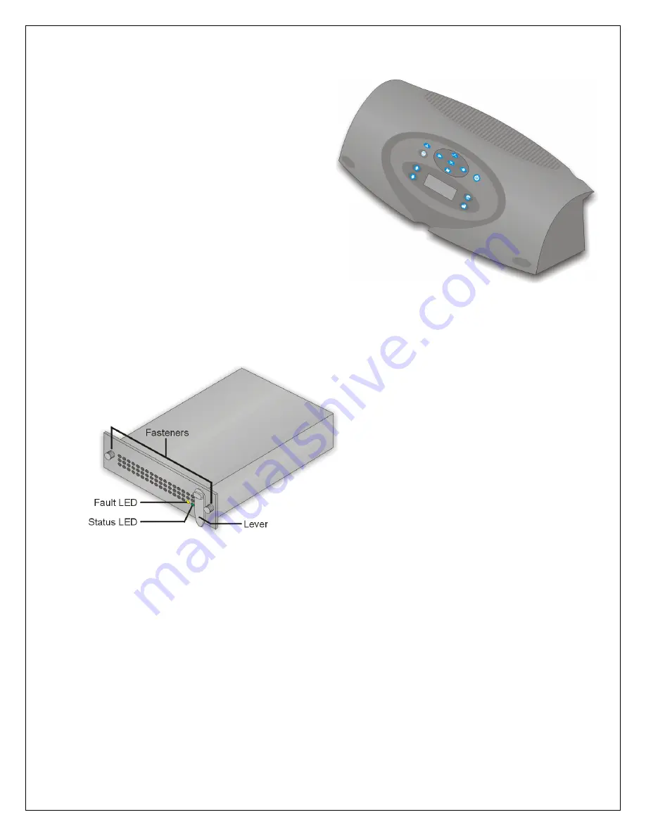
System Control Module
The System Control Module is the
communicative backbone of the UPS. It
gathers input from all modules and processes
the data to control the operation of the
system – including monitoring the condition of
each module. An optional second System
Control Module can be installed to provide full
system functionality (operation and
communication), in the unlikely event a
Control Module should fail.
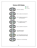
Under normal operation, the Status LED
(green) will blink and the Fault LED (amber)
will be off. For any condition other than this,
check the Troubleshooting section of this
manual.
User Interface Module
System Control Module
Summary of Contents for 12 bay
Page 1: ...User Manual English 208 V 240 V 60Hz 4 to 16 kVA Power System...
Page 2: ......
Page 4: ...2 Glossary of Symbols...
Page 5: ...3 Introduction General Description Modes of Operation Major Components...
Page 7: ...5...
Page 12: ...10 Installation Preparation Unloading Cable Installation Communications...
Page 20: ...18 Operating Instructions Controls and Indicators Operating Procedures Main Menu...
Page 33: ...31 Troubleshooting Alarm Messages Module LED Indication Module Replacement...
Page 38: ...36 Maintenance Proper Care Scheduled Maintenance Replacing Fan Filters...
Page 40: ...38 Reference Specifications Battery Run Times Warranty Technical Support...


