11
These installation instructions provide all the
information needed for positioning the UPS
(including environmental requirements) and for
connecting the input and output power cables.
Inspection
Upon receiving the UPS, examine the packaging
for any signs of mishandling or damage. If any
damage is noted, call your local Liebert
representative and/or notify your carrier.
Environment
Note:
Operating in temperatures above 77° F
(25° C) will reduce battery life. The UPS
environment must be free of conductive
contaminants and excessive moisture (water
condensation, flammable vapors, chemical
fumes, or corrosive gasses and liquids).
Required Setup Equipment
The tools below are required in order to properly
setup your UPS:
§
Pallet jack
§
1/2” (13mm) ratchet or wrench
§
Torque Wrench (in / lb)
§
Flathead Screwdriver
§
#2 Phillips Screwdriver
Site Preparation
When deciding where to locate your UPS,
consider the weight and size of the unit. Make
sure that the structural integrity of the floor can
withstand the weight of a fully loaded unit. Refer
to the table below for size and fully populated
weight considerations:
Model
Max Weight
H x W x D
8 bay
871
40” x 20” x 28”
12 bay
1186
53” x 20” x 28”
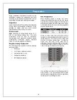
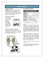
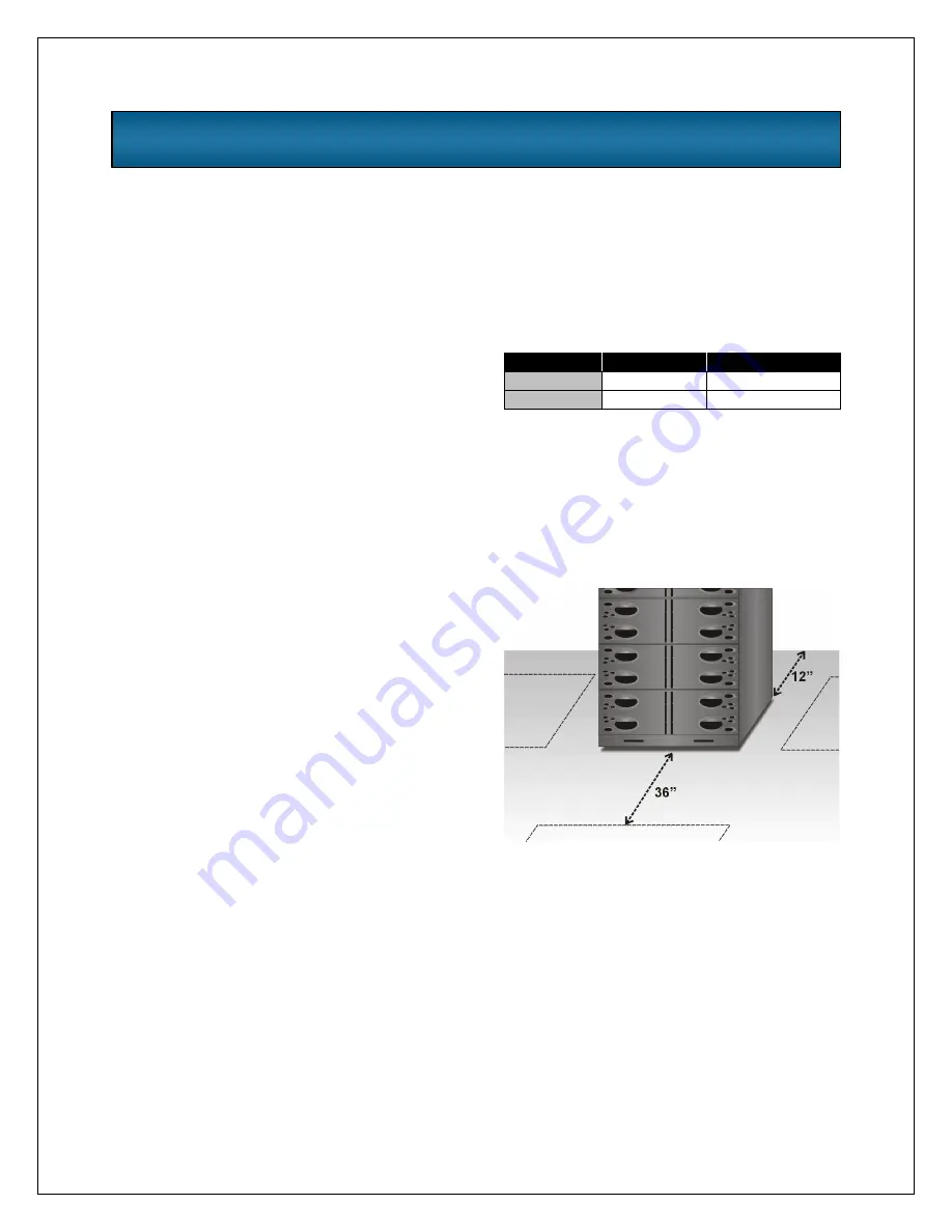
Check to make sure that your UPS will be
located in a well-ventilated area with at least 12
inches behind it. The UPS is force cooled with
the aid of internal cooling fans. Cooling air
enters from the front of the UPS and is
exhausted through ventilation grills in the back.
It should also have at least 36 inches in front, in
order to change modules when necessary.
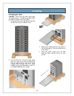
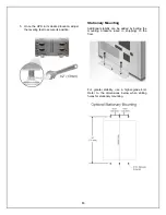
The unit frame is bolted to the shipping pallet to
ensure safety. It is recommended that a pallet
jack be used to transport the unit to its operating
location (prior to unbolting the unit).
Preparation
Summary of Contents for 12 bay
Page 1: ...User Manual English 208 V 240 V 60Hz 4 to 16 kVA Power System...
Page 2: ......
Page 4: ...2 Glossary of Symbols...
Page 5: ...3 Introduction General Description Modes of Operation Major Components...
Page 7: ...5...
Page 12: ...10 Installation Preparation Unloading Cable Installation Communications...
Page 20: ...18 Operating Instructions Controls and Indicators Operating Procedures Main Menu...
Page 33: ...31 Troubleshooting Alarm Messages Module LED Indication Module Replacement...
Page 38: ...36 Maintenance Proper Care Scheduled Maintenance Replacing Fan Filters...
Page 40: ...38 Reference Specifications Battery Run Times Warranty Technical Support...


