71
■
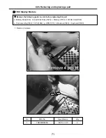
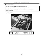
1100 Display Module
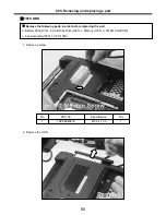
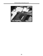
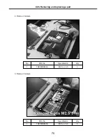
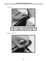
1. Remove 4 screws.
※
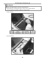
Remove the following parts in order before replacing this part
a. Battery Pack(1010) b. Hard Disk Drive(1020) c. Memory(1030) d. WLAN Card(1040)
e. Fan Assembly(1050) f. CPU(1060) g. ODD(1070) h. Retainer(1080) i. Keyboard(1090)
2
M2.5 x L8.0
1SZZBZ4046A
1
Qty
Specification
FRU No.
No.
Ch5. Removing and replacing a part
Summary of Contents for K1
Page 1: ...0 Service Manual K1 LG Electronics ...
Page 18: ...17 System Block Diagram Ch3 System information ...
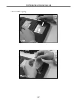
Page 58: ...57 3 Remove HDD using a tag Ch5 Removing and replacing a part ...
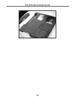
Page 59: ...58 Ch5 Removing and replacing a part ...
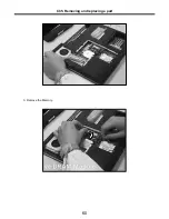
Page 61: ...60 3 Remove the Memory Ch5 Removing and replacing a part ...
Page 67: ...66 Ch5 Removing and replacing a part ...
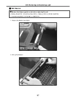
Page 69: ...68 3 Disconnect the Connector 4 Remove the Retainer Ch5 Removing and replacing a part ...
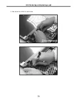
Page 73: ...72 2 Disconnect the LVDS Inverter Cable Ch5 Removing and replacing a part ...
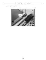
Page 74: ...73 3 Remove the Display Module Ch5 Removing and replacing a part ...
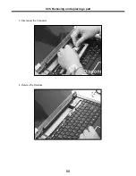
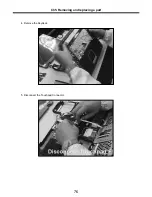
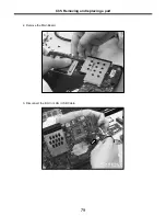
Page 77: ...76 4 Remove the Keydeck 5 Disconnect the Touchpad Connector Ch5 Removing and replacing a part ...
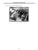
Page 78: ...77 6 Disconnect the Power Cable then remove the Keydeck Ch5 Removing and replacing a part ...
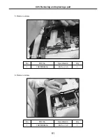
Page 81: ...80 4 Disconnect the MDC Cable Ch5 Removing and replacing a part ...
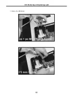
Page 83: ...82 7 Remove the USB Board Ch5 Removing and replacing a part ...
Page 90: ...K1 Buffalo EXPLODED VIEW 2 NHDDB NCVRH NSCRF NSCRF NSCRF NSCRF NBRKB ...

