19
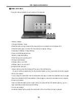
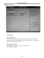
Status indicators
Ch3. System information
The system status indicators show the status of the computer
1. Battery Indicator
- Charging the battery: Green
- When the battery is fully charged or the computer is not connected to an AC Adapter: OFF
- When the battery power is under 10% of its maximum capacity: Orange
- The battery is defective: Orange blinking
2. Power On/Off/Suspend Indicator
- Stand by mode: Red blinking
- When the System is operating: OFF
3. Wireless LAN Indicator
- Wireless LAN is in use: ON
- Wireless LAN is not in use: OFF
4. Hard disk drive indicator
- Indicator lights up when the Notebook PC access to the hard disk drive.
※
Do not turn off the computer when the drive indicator lights up. It may cause data loss to the computer.
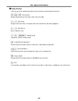
5. Num Lock Indicator
- You can press the combination of [Fn] and [Ins(Num Lk)] keys to enable the embedded numeric keypad.
Press the combination of [Fn] and [Ins(Num Lk)] keys again to disable the embedded numeric keypad.
6. Caps Lock Indicator
- Caps Lock indicator lights up when Caps Lock key is pressed. When this indicator lights up, you can
type capital letters without pressing the Shift key.
7. Scroll Lock Indicator
- ScrollLock indicator lights up when the combination of the Fn and Num lock key is pressed.
Summary of Contents for K1
Page 1: ...0 Service Manual K1 LG Electronics ...
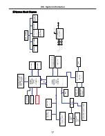
Page 18: ...17 System Block Diagram Ch3 System information ...
Page 58: ...57 3 Remove HDD using a tag Ch5 Removing and replacing a part ...
Page 59: ...58 Ch5 Removing and replacing a part ...
Page 61: ...60 3 Remove the Memory Ch5 Removing and replacing a part ...
Page 67: ...66 Ch5 Removing and replacing a part ...
Page 69: ...68 3 Disconnect the Connector 4 Remove the Retainer Ch5 Removing and replacing a part ...
Page 73: ...72 2 Disconnect the LVDS Inverter Cable Ch5 Removing and replacing a part ...
Page 74: ...73 3 Remove the Display Module Ch5 Removing and replacing a part ...
Page 77: ...76 4 Remove the Keydeck 5 Disconnect the Touchpad Connector Ch5 Removing and replacing a part ...
Page 78: ...77 6 Disconnect the Power Cable then remove the Keydeck Ch5 Removing and replacing a part ...
Page 81: ...80 4 Disconnect the MDC Cable Ch5 Removing and replacing a part ...
Page 83: ...82 7 Remove the USB Board Ch5 Removing and replacing a part ...
Page 90: ...K1 Buffalo EXPLODED VIEW 2 NHDDB NCVRH NSCRF NSCRF NSCRF NSCRF NBRKB ...


