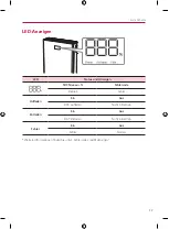
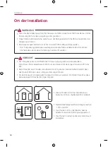

Installation
31
E
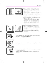
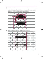
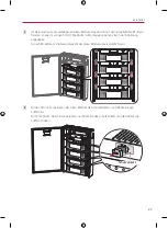
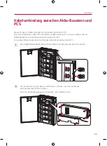
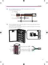
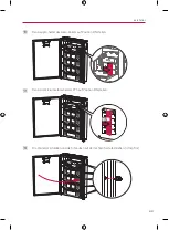
Wie in der Abbildung gezeigt, an der Seite des Akku-Baustein die 3-poligen
Kommunikationskabel abisolieren.
12 mm
50 mm
Blau
Braun
Grün
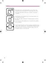
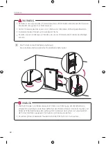
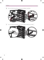
F
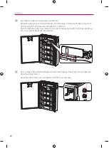
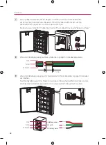
Wie in der Abbildung gezeigt, an der Klemmleiste für Kommunikationskabel das
3-polige
Kommunikationskabel anschließen.
Bei Anschluss an LG ESS PCS beachten Sie im PCS-Handbuch das Kapitel "Kommunikations-
Anschlüsse ATS, BMS, EV-ZÄHLER".
3. RS485_Low (At PCS: Port 18)
4. RS485_High (At PCS: Port 17)
6. Shield Earth (At PCS: Port 16)
Blau
Braun
Grün
Summary of Contents for BUEL011HBC1
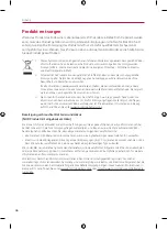
Page 46: ...Appendix 46 Wiring Diagram BUEL011HBC1 Pack 3 BCU Enclosure BUEL015HBC1 Pack 4 BCU Enclosure ...
Page 47: ...Appendix 47 ...
Page 48: ......
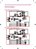
Page 93: ...Anhang 45 Elektroschaltplan BUEL011HBC1 Paket 3 BCU Gehäuse BUEL015HBC1 Paket 4 BCU Gehäuse ...
Page 94: ......
Page 140: ......


