


Installation
31
E
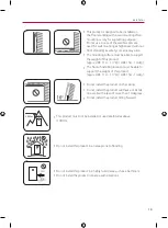
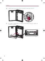
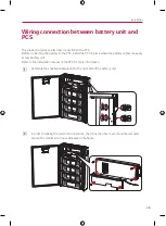
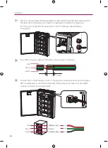
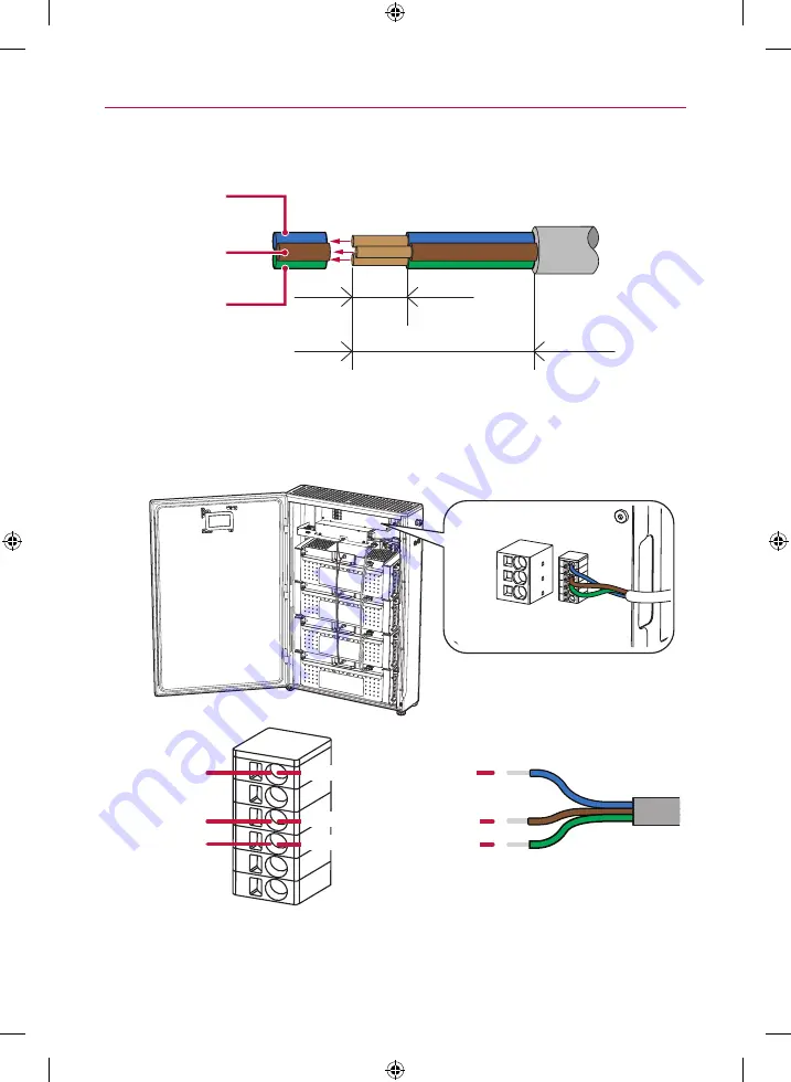
Strip off the 3-conductor communication wires at the battery unit as shown in the figure.
12 mm
50 mm
Blue
Brown
Green
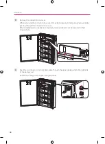
F
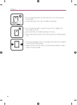
Connect the
3-conductor communication wires to the communication terminal block as
shown in the figure.
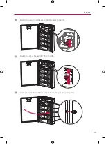
For connection at LG ESS PCS, please refer to the PCS manual chapters "ATS, BMS, EV
METER Communication Connections".
3. RS485_Low (At PCS: Port 18)
4. RS485_High (At PCS: Port 17)
6. Shield Earth (At PCS: Port 16)
Blue
Brown
Green
Summary of Contents for BUEL011HBC1
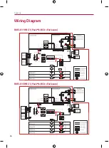
Page 46: ...Appendix 46 Wiring Diagram BUEL011HBC1 Pack 3 BCU Enclosure BUEL015HBC1 Pack 4 BCU Enclosure ...
Page 47: ...Appendix 47 ...
Page 48: ......
Page 93: ...Anhang 45 Elektroschaltplan BUEL011HBC1 Paket 3 BCU Gehäuse BUEL015HBC1 Paket 4 BCU Gehäuse ...
Page 94: ......
Page 140: ......


