


Installation
30
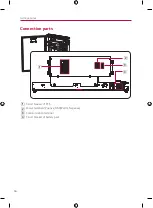
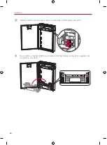
c
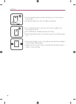
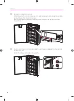
Remove the connection box cover.
When removing the connection box cover, it may be necessary to temporarily remove cables
passing through the connection box cover.
After completing all connections, temporarily removed cables must be restored to their
original state.
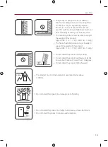
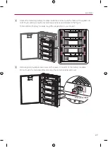
D
Pass the 3-conductor communication cable through the upper cable gland to the right side
of the battery unit.
Rotate the cable gland to tighten the gland hole.
Summary of Contents for BUEL011HBC1
Page 46: ...Appendix 46 Wiring Diagram BUEL011HBC1 Pack 3 BCU Enclosure BUEL015HBC1 Pack 4 BCU Enclosure ...
Page 47: ...Appendix 47 ...
Page 48: ......
Page 93: ...Anhang 45 Elektroschaltplan BUEL011HBC1 Paket 3 BCU Gehäuse BUEL015HBC1 Paket 4 BCU Gehäuse ...
Page 94: ......
Page 140: ......


