


Installation
29
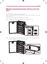
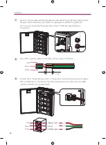
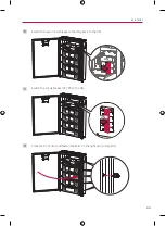
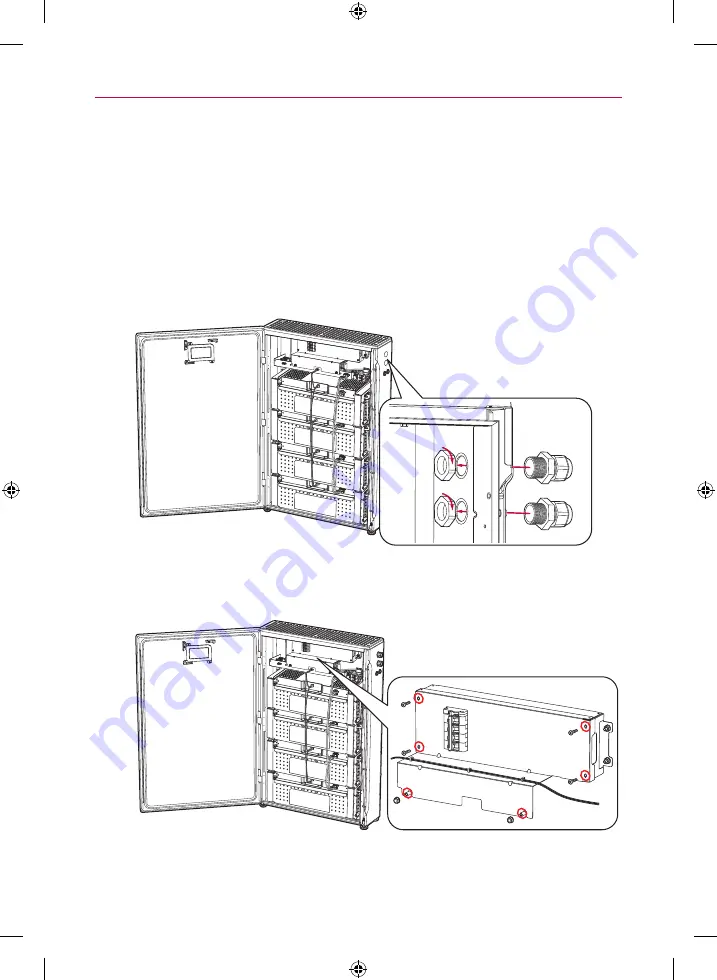
Wiring connection between battery unit and
PCS
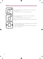
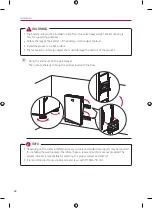
This product requires an electrical connection to the PCS.
Before connecting the battery to the PCS, install the PCS in place where the battery cables can easily
access battery unit.
Refer to the installation manual of the PCS for more information.
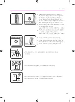
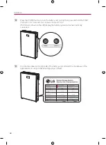
a
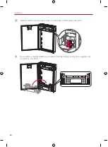
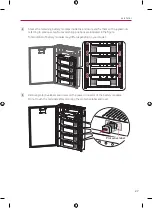
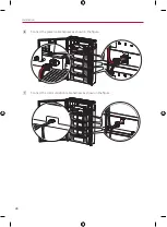
Assemble the supplied cable glands to the right side of the battery unit.
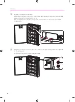
b
In order to making the electrical connections, the connection box cover should be removed.
Loosen the 4 bolts and 2 nuts indicated in the figure.
Summary of Contents for BUEL011HBC1
Page 46: ...Appendix 46 Wiring Diagram BUEL011HBC1 Pack 3 BCU Enclosure BUEL015HBC1 Pack 4 BCU Enclosure ...
Page 47: ...Appendix 47 ...
Page 48: ......
Page 93: ...Anhang 45 Elektroschaltplan BUEL011HBC1 Paket 3 BCU Gehäuse BUEL015HBC1 Paket 4 BCU Gehäuse ...
Page 94: ......
Page 140: ......


