background image

4

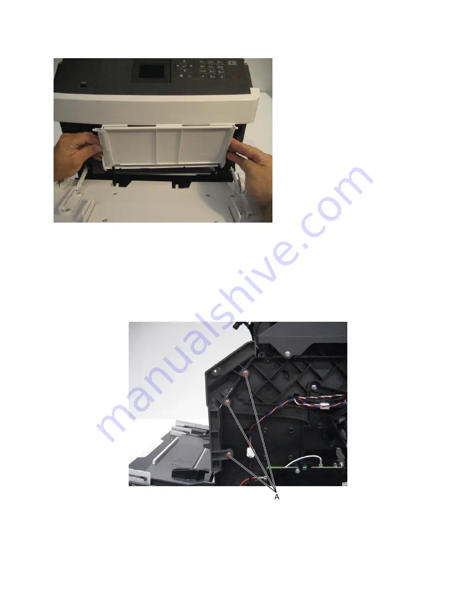
Raise the MPF tray to a vertical position, and detach it from the machine.

Right inner cover removal

1

Open the front door.

2

Raise the control panel to its uppermost position.

3

Remove the right cover. See 

“Right cover removal” on page 505

.

4

Remove the three screws (A) securing the right inner cover to the machine.

4063

Repair information

406

Summary of Contents for M5170

Page 1: ...MS71x MS81x M51xx Machine Type 4063 2xx 4xx 63x 83x Service Manual Start diagnostics Maintenance Safety and notices Trademarks Index August 23 2013 www lexmark com P N 12G3023 ...

Page 2: ... product program or service is not intended to state or imply that only that product program or service may be used Any functionally equivalent product program or service that does not infringe any existing intellectual property right may be used instead Evaluation and verification of operation in conjunction with other products programs or services except those expressly designated by the manufac...

Page 3: ...ffice papers 44 Using specialty media 45 Tips on using card stock 45 Tips on using envelopes 46 Tips on using labels 46 Tips on using letterhead 46 Tips on using transparencies 47 Supported paper sizes types and weights 47 Paper types and weights supported by the printer 47 Paper sizes supported by the printer 48 Paper sizes types and weights supported by the optional finishers 49 Data security no...

Page 4: ... motor control jam service check 76 Fuser drive motor control jam service check 76 Sensor input miscellaneous jam 1 service check 76 Sensor input miscellaneous jam 2 service check 77 Sensor input miscellaneous jam 3 service check 77 202 paper jams 78 x page jam open upper rear door 202 78 202 paper jam messages 79 Sensor fuser exit static jam service check 80 Sensor fuser exit late leaving jam ser...

Page 5: ...23 x page jam remove paper open expander rear door Leave paper in bin 41y xx 123 x page jam remove paper open mailbox rear door Leave paper in bin 43y xx 124 x page jam remove paper open finisher rear door Leave paper in bin 451 126 x page jam remove paper open stapler door Leave paper in bin 455 457 127 4yy paper jam messages 130 Sensor mailbox pass through jam service check 139 Mailbox main moto...

Page 6: ...ter jam service check 211 Understanding the printer messages 213 Cartridge imaging unit mismatch 41 xy 213 Cartridge low 88 xy 213 Cartridge nearly low 88 xy 213 Cartridge very low x estimated pages remain 88 xy 213 Change paper source to custom string load orientation 213 Change paper source to custom type name load orientation 214 Change paper source to paper size load orientation 214 Change pap...

Page 7: ...anual feeder with paper type paper size paper orientation 221 Maintenance kit low 80 xy 221 Maintenance kit nearly low 80 xy 221 Maintenance kit very low x estimated pages remain 80 xy 222 Memory full 38 222 Network x software error 54 222 Non Lexmark supply type see User s Guide 33 xy 222 Not enough free space in flash memory for resources 52 223 PPDS font error 50 223 Paper changes needed 223 Pa...

Page 8: ...s 230 User attendance messages 0 99 99 230 Toner level sensing error check 235 Toner cartridge smart chip error service check 236 Imaging unit smart chip service check 236 Fuser unit smart chip service check 237 Printer hardware errors 237 1yy error messages 238 Printhead ID service check 242 Printhead service check 242 Fuser drive motor service check 243 Fuser service check 243 LVPS service check...

Page 9: ...edia error service check 287 HCIT media type error service check 289 HCIT undetected service check 291 HCIT media low undetected service check 293 Mailbox incorrect bin exit service check 295 Mailbox undetected service check 297 Finisher side door error service check 298 Finisher cartridge error service check 300 Finisher undetected service check 301 Finisher bin error service check 302 Finisher d...

Page 10: ... Test 325 Button Test 325 DRAM Test 326 Serial Wrap Test 326 USB HS Test Mode 327 DUPLEX TESTS 327 Quick Test 327 Top Margin 328 Sensor Test 328 Motor Test 329 Duplex Feed 1 329 Duplex Feed 2 329 INPUT TRAY TESTS 330 Feed Tests 330 Sensor Tests 330 OUTPUT BIN TESTS 331 Feed Tests 331 Feed To All Bins 331 Sensor Test 331 Diverter Test 331 FINISHER TESTS 332 Staple Test 332 Hole Punch Test 332 Feed ...

Page 11: ... Adj 338 REPORTS 339 Menu Settings Page 339 Installed Licenses 339 EVENT LOG 339 Display Log 339 Print Log 340 Clear Log 340 Exit Diags 340 Configuration menu 340 Entering the Configuration menu 341 Roller Kit Counter Value 342 Reset Roller Kit Counter 342 Print Quality Pages 342 Reports 343 Menu Settings Page 343 Event Log 343 Size sensing 343 Panel Menus 344 PPDS Emulation 344 Download Emuls 344...

Page 12: ...ion 355 Removal precautions 355 Handling ESD sensitive parts 355 Controller board control panel replacement 356 Restoring the printer configuration after replacing the controller board 357 eSF solutions backup 359 Ribbon cable connectors 360 Zero Insertion Force ZIF connectors 360 Horizontal top contact connector 361 Horizontal bottom contact connector 364 Vertical mount contact connector 367 Hori...

Page 13: ... board 2 4 inch tilting display removal 434 Control panel board 4 3 inch tilting display removal 437 Control panel board 7 inch tilting display removal MS812de 440 Control panel front cover removal 443 Control panel latch removal 445 Control panel left bezel removal 446 Left control panel hinge removal 447 Right control panel hinge removal 450 Rear side removals 453 Rear lower cover removal 454 Re...

Page 14: ... 500 Sensor control panel interlock removal 501 Sensor pick roller position removal 502 Toner add motor removal 503 Right side removals 504 Right cover removal 505 Cartridge cooling fan removal 507 Duplex cooling fan removal 508 Fuser cooling fan removal 509 HVPS removal 510 LVPS removal 511 250 550 sheet media tray option removals 514 250 550 sheet media tray and drawer assembly removal 514 Media...

Page 15: ...ia feeder removal 551 Output expander option removals 554 Output expander option removal 554 Output expander top cover removal 554 Output expander rear door removal 555 Output expander sensor cover removal 557 Output expander bin full flag removal 557 Sensor media bin full with flag removal 557 Output expander right cover removal 558 Output expander left cover removal 560 Output expander controlle...

Page 16: ...y spring removal 597 HCOE tray pinion removal 598 Sensor HCOE rear door interlock removal 599 HCOE belt tensioner removal 601 HCOE drive belt removal 602 HCOE diverter plunger assembly removal 604 HCOE main drive gear assembly removal 605 HCOE main motor removal 607 Sensor HCOE diverter HP removal 609 HCOE top diverter spring removal 611 HCOE top diverter removal 612 HCOE tray shaft removal 614 HC...

Page 17: ...3 Stapler main motor removal 664 Stapler diverter motor removal 666 Stapler diverter plunger assembly removal 667 Stapler drive gear assembly removal 668 Sensor bin full send removal 669 Sensor bin full receive removal 670 Media pusher assembly removal 672 Stapler feed roll removal 672 Stapler chute assembly removal 674 Sensor stapler pass through removal 677 Stapler ejector motor assembly removal...

Page 18: ...e hole punch left cover removal 739 Staple hole punch right cover removal 741 Sensor cartridge door interlock removal 742 Stapler door close limit switch removal 743 Stapler carriage assembly removal 746 Sensor throat media present removal 747 Staple hole punch latch removal 749 Stapler controller PCBA removal 749 Stapler main motor removal 750 Stapler paddle motor removal 751 Sensor paddle motor ...

Page 19: ...ed maintenance 793 Fuser maintenance kits 793 Replacing fuser maintenance kits 794 Identifying the type of fuser used in the printer 795 Resetting the Roller Kit counter 796 Preventive maintenance 797 Device specific preventive maintenance 797 Lubrication specification 797 Cleaning the printer 797 Cleaning the printer 797 Emptying the hole punch box 798 Parts catalog 800 Legend 801 Assembly 1 Cove...

Page 20: ...Assembly 23 High capacity output expander option 4 853 Assembly 24 Staple finisher option 1 855 Assembly 25 Staple finisher option 2 857 Assembly 26 Staple finisher option 3 859 Assembly 27 Staple finisher option 4 861 Assembly 28 Mailbox option 1 863 Assembly 29 Mailbox option 2 865 Assembly 30 Mailbox option 3 867 Assembly 31 Staple hole punch finisher option 1 869 Assembly 32 Staple hole punch ...

Page 21: ...89 Media feeder assembly 890 Media feeder 890 Sensor media size 890 Sensor pick roller position 890 Multi purpose feeder MPF 890 MPF pick roller 891 MPF pick solenoid 891 Registration 891 Sensor input 892 Duplex 892 Sensor duplex path 892 Transfer 892 Transfer roller 892 Printhead 893 Fuser components 894 Heat belt belt fuser 895 Heat belt hot roll fuser 895 Pressure roll 895 Heater lamp hot roll ...

Page 22: ...ng fan 899 Duplex cooling fan 899 Fuser cooling fan hot roll printer only 899 LVPS board assembly 900 HVPS board assembly 900 Controller board 900 Xerographic and print cartridge components 900 Output options theory 904 Output expander theory 904 High capacity output expander theory 905 Mailbox theory 906 Staple finisher theory 907 Appendix D Acronyms 909 Acronyms 909 Index 911 Part number index 9...

Page 23: ...setzt sind die die Werte für Klasse I überschreitet Avis relatif à l utilisation du laser L imprimanteestcertifiéeconformeauxexigencesdelaréglementationdesEtats Unis relativeauxproduits laser DHHS 21CFR Chapter I Subchapter J for Class I 1 Pour les autres pays elle est certifiée conforme aux exigences des normes IEC 60825 1 relatives aux produits laser de classe I Les produits laser de Classe I ne...

Page 24: ...as Laserinformatie Deze printer is in de Verenigde Staten gecertificeerd als een product dat voldoet aan de vereisten van DHHS 21 CFR hoofdstuk 1 paragraaf J voor laserproducten van klasse I 1 Elders is de printer gecertificeerd als een laserproduct van klasse I dat voldoet aan de vereisten van IEC 60825 1 Laserproducten van klasse I worden geacht geen gevaar op te leveren De printer bevat intern ...

Page 25: ...laser og somopererer ibølgelengder på 787 800nanometer Lasersystemet og skriveren er utformet slik at mennesker ikke utsettes for laserstråling utover nivået i klasse I under normal drift vedlikehold eller foreskrevet service Avís sobre el làser AlsEUA laimpressoraestàcertificadadeconformitatambelsrequisitsdelcapítolI apartatJdelCFR21delDepartament de Salut i Serveis Humans per a productes làser d...

Page 26: ...mation for this product has been prepared for use by a professional service person and is not intended to be used by others There maybean increased riskofelectricshockand personal injuryduring disassemblyandservicing ofthis product Professional service personnel should understand this and take necessary precautions CAUTION POTENTIAL INJURY The lithium battery in this product is not intended to be ...

Page 27: ...twortung oder Haftung für die Sicherheit übernommen Die Wartungsinformationen für dieses Produkt sind ausschließlich für die Verwendung durch einen Wartungsfachmann bestimmt Während des Auseinandernehmens und der Wartung des Geräts besteht ein zusätzliches Risiko eines elektrischen Schlags und körperlicher Verletzung Das zuständige Fachpersonal sollte entsprechende Vorsichtsmaßnahmen treffen VORSI...

Page 28: ...utilitzen peces de recanvi no autoritzades La informació pel manteniment d aquest producte està orientada exclusivament a professionals i no està destinada a ningú que no ho sigui El risc de xoc elèctric i de danys personals pot augmentar durant el procés de desmuntatge i de servei d aquest producte El personal professional ha d estar ne assabentat i prendre les mesures convenients ATENCIÓ La bate...

Page 29: ...当心一可能的伤害 本产品中的锂电池不可更换 如果不正确更换锂电池 可能会有爆炸危险 不要再 充电 拆解或 焚烧锂电池 丢弃旧的锂电池时应按照制造商的指导及当地法规进行处理 4063 Notices and safety information 29 ...

Page 30: ...4063 30 ...

Page 31: ...he product Appendix C Theory of operation contains the theory of operation Appendix D Acronyms contains the list of acronyms in the manual and their meanings Service manual conventions Note A note provides additional information Warning Potential Damage A warning identifies something that might damage the product hardware or software This service manual uses several different types of caution stat...

Page 32: ...er 40X8715 Output expander sensor cover 40X8712 Output expander bin full flag High capacity output expander option FRUS 40X8730 HCOE main motor 40X8721 HCOE option latch 40X8256 HCOE diverter motor 40X8731 HCOE Tray pinion 40X8733 HCOE Tray spring 40X7592 Sensor HCOE rear door interlock 40X8728 Sensor HCOE tray HP 40X8726 HCOE main drive gear assembly 40X8722 HCOE diverter plunger assembly 40X7592...

Page 33: ...nsor stapler pass through 40X8214 Stapler rear door Mailbox option FRUs 40X8739 Mailbox main motor 40X7592 Sensor mailbox rear door interlock 40X8721 Mailbox option latch 40X8726 Mailbox main drive gear 40X8722 Mailbox diverter plunger assembly 40X8196 Mailbox top cover 40X8720 Mailbox top bin cover with bail 40X8719 Sensor mailbox pass through 40X8725 Mailbox top diverter spring 40X8723 Mailbox t...

Page 34: ...ce check Finisher HPU ejector jam service check Sensor HPU finisher pass through jam service check Finisher HPU left tamper jam service check Finisher HPU right tamper jam service check Finisher HPU diverter jam service check Finisher HPU paddle jam service check Finisher HPU tray holder jam service check Sensor HPU throat media present jam service check Stapler carriage HPU jam service check HPU ...

Page 35: ...r removal Sensor cartridge door interlock removal Stapler door close limit switch removal Stapler carriage assembly removal Sensor throat media present removal Staple hole punch latch removal Stapler controller PCBA removal Stapler main motor removal Stapler paddle motor removal Sensor paddle motor HP removal Stapler diverter motor removal Stapler diverter plunger assembly removal Stapler drive ge...

Page 36: ... revised 3xx error messages 300 399 99 4xx error messages 400 499 99 Option tray symptoms Sensor mailbox pass through jam service check Mailbox diverter jam service check HCOE diverter jam service check Sensor HCOE pass through jam service check Sensor finisher pass through jam service check Finisher left tamper jam service check Finisher right tamper jam service check Finisher ejector jam service...

Page 37: ...ble entries in Miscellaneous parts catalog assembly The following Option related topics were added Output expander option removals Output expander option latch removal Output expander diverter motor removal Output expander diverter plunger assembly removal Output expander main motor removal Sensor OE rear door interlock removal Sensor OE diverter plunger HP removal Output expander diverter spring ...

Page 38: ...utput bin LED removal Stapler main motor removal Stapler diverter motor removal Stapler diverter plunger assembly removal Stapler drive gear assembly removal Media pusher assembly removal Stapler feed roll removal Stapler chute assembly removal Sensor stapler pass through removal Stapler ejector motor assembly removal Sensor stapler ejector HP removal Sensor media pusher HP removal Mailbox option ...

Page 39: ... procedure February 4 2013 10 xx and 24x 08 errors were added to the User attendance messages table 24x 08 errors were added to the 24x paper jams and Input option jam error messages tables New topic for updating the firmware was added to the Service menus chapter BSD machines were added to the list of models under the General information chapter 4063 Preface 39 ...

Page 40: ...4063 40 ...

Page 41: ...Network 4 3 e Task touch screen duplex printer 4063 23E M5155 4063 29E M5163 4063 49E MS811n Network 4063 410 M5163dn 4063 490 MS811dn Network duplex printer 4063 430 MS812dn Network duplex printer 4063 630 MS812de Network 7 e Task touch screen duplex printer 4063 63E The diagnostic information in this manual leads you to the correct field replaceable unit FRU or part Use the error code charts sym...

Page 42: ...posed to high temperatures Storing paperunwrapped inhot humid cold or dry conditions even in the trays can contribute to paper curling prior to printing and can cause feeding problems Smoothness Paper smoothness directly affects print quality If paper is too rough toner cannot fuse to it properly If paper is too smooth it can cause paper feeding or print quality issues Always use paper between 100...

Page 43: ...er weighing less than 60 g m2 16 lb Multiple part forms or documents Selecting paper Using the appropriate paper prevents jams and helps ensure trouble free printing To help avoid paper jams and poor print quality Always use new undamaged paper Before loading paper know the recommended printable side of the paper This information is usually indicated on the paper package Do not use paper that has ...

Page 44: ...ontent Business papers should have low moisture 4 5 Bending resistance and proper stiffness means optimum feeding through the printer Thickness impacts how much can be loaded into a tray Surface roughness measured in Sheffield units impacts print clarity and how well toner fuses to the paper Surface friction determines how easily sheets can be separated Grain and formation impacts curling which al...

Page 45: ...he printer fuser Preprinted papers that require a registration the precise location on the page greater than 2 3 mm 0 9 in such as optical character recognition OCR forms In some cases registration can be adjusted with a software application to successfully print on these forms Coated papers erasable bond synthetic papers thermal papers Rough edged rough or heavily textured surface papers or curle...

Page 46: ...ination of high humidity over 60 and high printing temperature may wrinkle or seal envelopes Tips on using labels From the printer control panel set the paper size type texture and weight in the Paper menu to match the labels loaded in the tray Print samples on labels being considered for use before buying large quantities For more information on label printing characteristics and design see the C...

Page 47: ... transparencies designed specifically for laser printers Avoid getting fingerprints on the transparencies to prevent print quality problems Before loading transparencies flex and fan the sheets to prevent them from sticking together When printing on large volumes of transparencies make sure to print by batches of only up to 20 with an interval of at least three minutes between batches to prevent t...

Page 48: ... 297 mm 8 3 x 11 7 in A5 148 x 210 mm 5 8 x 8 3 in A6 105 x 148 mm 4 1 x 5 8 in X JIS B5 182 x 257 mm 7 2 x 10 1 in X Letter 216 x 279 mm 8 5 x 11 in Legal 216 x 356 mm 8 5 x 14 in Executive 184 x 267 mm 7 3 x 10 5 in X Oficio 216 x 340 mm 8 5 x 13 4 in Folio 216 x 330 mm 8 5 x 13 in Statement 140 x 216 mm 5 5 x 8 5 in X Universal 105 x 148 mm to 216 x 356 mm 4 13 x 5 83 in to 8 5 x 14 in X 70 x 1...

Page 49: ... it is loaded long edge first 3 The finisher stacks and staples the paper but does not punch holes in it 4 The finisher staples the paper if its width is between 8 27 and 8 54 inches Supported paper types and weights Paper type Paper weight 4 bin mailbox Offset stacker Staple finisher Staple hole punch finisher Plain paper 90 176 g m2 24 47 lb X X X X 60 90 g m2 16 24 lb Card stock 163 g m2 90 Ib ...

Page 50: ... X X Polyester 220 g m2 59 Ib X X X X Bond 90 176 g m2 24 47 lb X X X X 60 90 g m2 16 24 lb Envelope 105 g m2 28 Ib X X X X Letterhead 90 176 g m2 24 47 lb X X X X 60 90 g m2 16 24 lb Preprinted 90 176 g m2 24 47 lb X X X X 60 90 g m2 16 24 lb Colored paper 90 176 g m2 24 47 lb X X X X 60 90 g m2 16 24 lb Light paper 60 90 g m2 16 24 lb Heavy paper 60 90 g m2 16 24 lb The finisher stacks the paper...

Page 51: ...gned for device specific functionality and cannot be used for long term storage for data that is not print related The hard disk doesnotprovidethecapabilityforuserstoextractinformation createfolders creatediskornetworkfileshares or transfer FTP information directly from a client device The hard disk can retain buffered user data from complex print jobs as well as form data and font data To erase v...

Page 52: ...al side cutters Spring hook Feeler gauges Analog or digital multimeter Parallel wrap plug 1319128 Twinax serial debug cable 1381963 Coax serial debug cable 1381964 Flashlight optional 3 mm hex wrench 5 5 mm hex wrench 4063 General information 52 ...

Page 53: ...leshooting overview Performing the initial troubleshooting check on page 53 Power on Reset POR sequence on page 54 Using Safe Mode on page 54 Performing the initial troubleshooting check Before you start the troubleshooting procedures perform the following checks With the power cord unplugged from the electrical outlet check that the cord is free from the breakage short circuits disconnected wires...

Page 54: ...ssues See Safe Mode print behavior on page 54 Warning Potential Damage Safe Mode is intended as a short term workaround and should be used only in the case of a non critical error when a print job must be completed before service can be arranged to repair the printer The printer must be returned to standard operating mode before diagnostics can be run or full function printing can continue You can...

Page 55: ...s on page 59 Skewed print on page 59 Streaked horizontal lines appear on prints on page 61 Streaked vertical lines appear on prints on page 62 Toner rubs off on page 63 The symptoms described in this chapter might require replacement of one or more CRUs Customer Replaceable Units designated as supplies or maintenance items which are the responsibility of the customer With the customer s permission...

Page 56: ...re can cause problems Incorrect characters could print and the copy may not fit the page correctly Gray background on prints ABCDE ABCDE ABCDE Leading edge Trailing edge Actions Yes No Step 1 Ensure the toner cartridge has sufficient toner Does the cartridge have sufficient toner Go to step 2 Replace the toner cartridge Step 2 Remove any contamination from the CTLS contacts located on the toner le...

Page 57: ... Check the transfer roller for surface contamination or excessive wear Is it free of contamination and wear Go to step 4 Replace the transfer roller Step 4 Check the transfer roller left contact spring located on the transfer roller left arm for damage Is it free of damage Go to step 5 Replace the transfer roller left arm with cable See Transfer roller left arm with cable removal on page 410 Step ...

Page 58: ... Are the above cables properly connected Replace the HVPS See HVPS removal on page 510 Reconnect the cables Repeating defects Actions Yes No Step 1 Measure the distance between defects Is the distance between defects equal to any of the following 3 81 in 96 8 mm 1 88 in 47 8 mm 1 12 in 28 5 mm Replace the imaging unit Go to step 2 Step 2 Is the distance between defects equal to 3 71 in 94 25 mm or...

Page 59: ...er roller for surface contamination or excessive wear Is it free of contamination and wear Go to step 4 Replace the transfer roller See Transfer roller removal on page 414 Step 4 Check the following fuser components for wear or damage Gears Exit rollers Heat belt or hot roller Are they free of damage Go to step 5 Replace the fuser See Fuser removal on page 459 Step 5 Reseat the connections on the ...

Page 60: ...l on page 482 Step 4 Check the lift plate on the media tray for damage Is it free of damage Go to step 11 Replacethemediatray Step 5 Make sure the MPF pick roller and separator pad are free of debris Check for wear or damage Are they free of wear or damage Go to step 6 Replace the MPF pick roller separator pad See MPF pick roller removal on page 400 Step 6 Perform the media skew adjustment See Med...

Page 61: ... settings to match the paper in the tray Step 3 Load paper from a fresh package Paper absorbs moisture due to high humidity Store paper in its original wrapper until you use it Does the problem remain Go to step 4 The problem is solved Step 4 Make sure the imaging unit or toner cartridge is not damaged a Remove the print or toner cartridge Warning Potential Damage Be careful not to touch the photo...

Page 62: ...amination and wear Is the above component free of excess wear and contamination Go to step 10 Replace the transfer roller See Transfer roller removal on page 414 Step 10 a Check the heat belt and hot roller in the fuser b Remove the fuser unit assembly CAUTION HOT SURFACE The inside of the printer might be hot To reduce the risk of injury from a hot component allow the surface to cool before touch...

Page 63: ...ened Go to step 2 Reseat the fuser and tighten the screws Step 2 Check the following fuser components for wear or damage Gears Exit rollers Heat belt or hot roller Are they free of damage Go to step 3 Replace the fuser See Fuser removal on page 459 Step 3 Check the cables on the LVPS Are the connections on the above component properly connected Contact the next level of support Replace the LVPS Se...

Page 64: ...d trays indicated on the display to remove the jam Notes When Jam Assist is set to On Discarding pages appears on the display and the printer flushes blank or pages with partial prints to the standard bin after a jammed page is cleared Check your printed output for blank pages When Jam Recovery is set to On or Auto the printer reprints jammed pages However the Auto setting reprints jammed pages if...

Page 65: ...ush down the front duplex flap and then remove the jammed paper 6 Trays x page jam open tray x 24x Pull out the indicated tray and then remove the jammed paper 7 Output expander x page jam remove paper open expander rear door Leave paper in bin 41y xx Open the rear door of the output expander and then remove the jammed paper 8 Upper rear door x page jam open upper rear door 202 Open the rear door ...

Page 66: ...ter might be hot To reduce the risk of injury from a hot component allow the surface to cool before touching 1 Lift the front cover and then pull down the multipurpose feeder door 2 Lift the green handle and then pull the toner cartridge out of the printer 3 Place the cartridge aside 4063 Diagnostic information 66 ...

Page 67: ...an 10 minutes Extended exposure to light may cause print quality problems 6 Pull the jammed paper gently to the right and then remove it from the printer Note Make sure all paper fragments are removed Warning Potential Damage The jammed paper may be covered with toner which can stain garments and skin 7 Install the imaging unit Note Use the arrows on the side of the printer as a guide 4063 Diagnos...

Page 68: ...ith the arrows in the printer Make sure the cartridge is fully pushed in 9 Close the multipurpose feeder door and the front cover 10 Do either of the following to clear the message and continue printing For touch screen printer models touch or Done For non touch screen printer models select Next Clear the jam press OK 4063 Diagnostic information 68 ...

Page 69: ...rinthead motor control jam service check on page 76 200 11 Printhead motor fell out of lock after the page reached the sensor input Go to Printhead motor control jam service check on page 76 200 12 Printhead was not ready for the page when the sensor input was reached Go to Printhead motor control jam service check on page 76 200 13 The page at the sensor input is not the next page to be imaged Go...

Page 70: ... jam service check Action Yes No Step 1 Check the media path for partially fed or jammed media Is the media path free from partially fed or jammed media Go to step 2 Remove any pre staged or jammed media Step 2 Check the sensor input for proper operation a Enter the diagnostic mode b Select Base sensor test c Observe the line item input Does the display on the operator panel change every time the ...

Page 71: ...7 Step 5 Check all the media trays for proper media installation Is the media properly installed in all the media trays Go to step 6 Remove and properly reinstall the media Step 6 Check all of the media trays and the media path for partially fed media Are the media trays and the media path free from any partially fed pieces of media Go to step 7 Remove any pre staged or jammed media Step 7 Check t...

Page 72: ...of the media trays crumpled or damaged Replace the damaged media Go to step 4 Step 4 Check media origination Did the media originate from the MPF Go to step 5 Go to step 7 Step 5 Check the MPF pick roll assembly Is the above component free of excess wear and contamination Go to step 6 Clean or replace the MPF pick roller See MPF pick roller removal on page 400 Step 6 Perform a MPF print test and c...

Page 73: ... is interrupted or blocked Go to step 12 Go to step 11 Step 11 Check the above sensor for proper connection Is the above sensor connected properly Replace the Sensor input See Sensor input removal on page 407 Replace the connection Step 12 Perform a print test and check the appropriate media feeder Is the media properly picked and advanced out of the appropriate media tray Go to step 13 Replace th...

Page 74: ...he media originate from the MPF Go to step 5 Go to step 7 Step 5 Check the MPF pick roll assembly Is the above component free of excess wear and contamination Go to step 6 Clean or replace the MPF pick roller See MPF pick roller removal on page 400 Step 6 Perform a MPF print test and check the MPF pick solenoid for proper operation Does the above component operate properly Go to step 9 Replace the...

Page 75: ... media feeder See Media feeder removal on page 498 Step 12 Perform a print test and check the main motor assembly Is the media properly transported and able to reach the sensor input Go to step 13 Replace the main drive motor See Maindrive motor removal on page 497 Step 13 Perform a print test Does the problem remain Contact the next level of technical support Problem solved Main drive motor contr...

Page 76: ...controller board for proper connection Is the main drive motor properly connected Replace the fuser drive motor See Fuser drive motor removal on page 494 Go to step 2 Reseat the connection Step 2 Reset the machine Does the error continue Replace the controller board See Controller board removal on page 492 Problem solved Sensor input miscellaneous jam 1 service check Action Yes No Step 1 Checkthea...

Page 77: ... above sensor is interrupted or blocked Go to step 3 Go to step 2 Step 2 Check the above sensor for proper connection Is the above sensor connected properly Replace the sensor control panel door interlock Go to step 3 Replace the connection Go to step 3 Step 3 Reset the machine Does the error continue Replace the controller board See Controller board removal on page 492 Problem solved Sensor input...

Page 78: ...pen upper rear door 202 CAUTION HOT SURFACE The inside of the printer might be hot To reduce the risk of injury from a hot component allow the surface to cool before touching 1 Pull down the rear door 2 Firmly grasp the jammed paper on each side and then gently pull it out Note Make sure all paper fragments are removed 4063 Diagnostic information 78 ...

Page 79: ...ia reached the sensor fuser exit but did not clear it within the specified time Go to Sensor fuser exit late leaving jam service check on page 81 202 07 The media reached the sensor fuser exit but did not clear it within the specified time Go to Sensor fuser exit late leaving jam service check on page 81 202 13 The media is late reaching the sensor fuser exit within the specified time Go to Sensor...

Page 80: ...ected wide page not detected by sensor narrow media possible accordion jam or missing signal Go to Sensor narrow media late arriving jam service check on page 83 202 43 The media is late reaching the sensor fuser exit within the specified time Go to Sensor fuser exit late arriving jam service check on page 82 202 45 Media remains on the sensor fuser exit during the warm up sequence Go to Sensor fu...

Page 81: ... change every time the sensing area of the above sensor is interrupted or blocked Go to step 5 Go to step 4 Step 4 Check the above sensor for proper connection Is the above sensor connected properly Replace the fuser See Fuser removal on page 459 Reseat the connection Step 5 Check the upper redrive for damage Is the above component free from damage Go to step 6 Replace the upper redrive See Upper ...

Page 82: ...ove sensor for proper connection Is the above sensor connected properly Replace the fuser See Fuser removal on page 459 Reseat the connection Step 5 Check the transfer roller for damage Is the above component free from damage Go to step 6 Replace the transfer roller See Transfer roller removal on page 414 Step 6 Check the media aligner roller for damage Is the above component free from damage Go t...

Page 83: ... 5 Step 5 Check the sensor narrow media for proper operation a Enter the diagnostic mode b Select Base sensor test c Observe the line item input Does the display on the operator panel change every time the sensing area of the above sensor is interrupted or blocked Go to step 7 Go to step 6 Step 6 Check the above sensor for proper connection Is the above sensor connected properly Replace the fuser ...

Page 84: ...ep 4 Reseat the connection Go to step 4 Step 4 Perform a print test Does the problem remain Contact the next highest level of technical support Problem solved Sensor fuser exit miscellaneous jam service check Action Yes No Step 1 Check the sensor fuser exit for proper operation a Enter the diagnostic mode b Select Base sensor test c Observe the line item fuser exit Does the display on the control ...

Page 85: ... connected Go to step 4 Reseat the connection Step 4 Ensure the LVPS connections are properly connected Are the above connections properly connected Go to step 5 Reseat the connections Step 5 Reset the machine Does the error continue ReplacetheLVPS Goto LVPS removal on page 511 Go to step 6 Problem solved Step 6 Reset the machine Does the error continue Replace the controller board See Controller ...

Page 86: ...motor control jam service check on page 86 Upper redrive motor control jam service check Action Yes No Step 1 Ensure the upper redrive area is free of media jams Is the upper redrive area free from media jams Go to step 2 Remove media jams Go to step 2 Step 2 Check the upper redrive for damage Is the upper redrive free from damage Go to step 3 Replace the upper redrive See Upper redrive removal on...

Page 87: ...nter might be hot To reduce the risk of injury from a hot component allow the surface to cool before touching 1 Pull down the rear door 2 Firmly grasp the jammed paper on each side and then gently pull it out Note Make sure all paper fragments are removed 3 Close the rear door 4063 Diagnostic information 87 ...

Page 88: ... standard tray 5 Press down the rear duplex flap then firmly grasp the jammed paper and then gently pull the paper out Note Make sure all paper fragments are removed 6 Insert the standard tray 4063 Diagnostic information 88 ...

Page 89: ...ly Note Lift the tray slightly and pull it out 2 Push down the front duplex flap then firmly grasp the jammed paper and then gently pull the paper to the right and out of the printer Note Make sure all paper fragments are removed 3 Insert the tray 4 Do either of the following to clear the message and continue printing For touch screen printer models touch or Done For non touch screen printer model...

Page 90: ...ath but did not clear it within the specified time Go to Sensor duplex path late leaving jam service check on page 93 230 20 Took too long to ramp up duplex motor Go to Duplex control jam service check on page 94 230 21 Duplex motor stopped after successful start up Go to Duplex control jam service check on page 94 230 22 Duplex motor under speed error Go to Duplex control jam service check on pag...

Page 91: ...and obstructions Go to step 2 Remove any jammed media or obstructions Step 2 Check the sensor duplex path for proper operation a Enter the diagnostic mode b Select duplex tests c Select sensor test d Observe the line item sensor Does the display on the control panel change every time the sensing area of the above sensor is interrupted or blocked Go to step 4 Go to step 3 Step 3 Check the above sen...

Page 92: ...ex path for proper operation a Enter the diagnostic mode b Select duplex tests c Select sensor test d Observe the line item sensor Does the display on the control panel change every time the sensing area of the above sensor is interrupted or blocked Go to step 6 Go to step 5 Step 5 Check the above sensor for proper connection Is the above sensor connected properly Replace the sensor duplex path Se...

Page 93: ...every time the sensing area of the above sensor is interrupted or blocked Go to step 5 Go to step 4 Step 4 Check the above sensor for proper connection Is the above sensor connected properly Replace the sensor duplex path See Sensor duplex path removal on page 484 Reseat the connection Step 5 Check the upper redrive for damage Is the above component free from damage Go to step 6 Replace the upper ...

Page 94: ... Replace the controller board See Controller board removal on page 492 Problem solved Sensor duplex path miscellaneous jam service check Action Yes No Step 1 Check the sensor duplex path for proper operation a Enter the diagnostic mode b Select duplex tests c Select sensor test d Observe the line item sensor Does the display on the control panel change every time the sensing area of the above sens...

Page 95: ...rupted or blocked Go to step 4 Go to step 3 Step 3 Check the above sensor for proper connection Is the above sensor connected properly Replace the sensor input See Sensor input removal on page 407 Replace the connection Step 4 Ensure the duplex motor cable and the socket DUPLEX MTR on the controller board is properly connected Is the above cable properly connected Go to step 5 Reseat the connectio...

Page 96: ... Check which tray is indicated on the printer display and then pull the tray 2 Firmly grasp the jammed paper on each side and then gently pull it out Note Make sure all paper fragments are removed 3 Insert the tray 4063 Diagnostic information 96 ...

Page 97: ...Media tray 1 tray pulled jam Go to Media tray 1 tray pulled jam on page 110 241 20 Tooktoolongtorampupmediafeedermotor in tray 1 Go to Media feeder motor control service check on page 109 241 21 Media feeder motor stall in tray 1 Go to Media feeder motor control service check on page 109 241 22 Media feeder motor pick motor under speed in tray 1 Go to Media feeder motor control service check on pa...

Page 98: ...550 sheet media tray option jam service check on page 113 242 08 HCIT A misfeed occurred due to shingling Themisfedmediaisflushedtotheoutputbin Press Continue to print using the next available media Go to HCIT jam service check on page 115 242 09 250 550 sheet tray Tray 2 pick motor lost encoder error Go to 250 550 sheet media tray option jam service check on page 113 242 09 HCIT Tray 2 pick motor...

Page 99: ... below Go to HCIT jam service check on page 115 242 18 250 550 sheet tray Failed to feed from tray 2 exhausted pick retries media committed to paper path Go to 250 550 sheet media tray option jam service check on page 113 242 18 HCIT Failed to feed from tray 2 exhausted pick retries media committed to paper path Go to HCIT jam service check on page 115 242 19 250 550 sheet tray Failed to feed from...

Page 100: ...42 42 HCIT Media feeder motor under speed in tray 2 Go to HCIT jam service check on page 115 242 43 250 550 sheet tray Media feeder motor did not reach the required speed Go to 250 550 sheet media tray option jam service check on page 113 242 43 HCIT Media feeder motor did not reach the required speed Go to HCIT jam service check on page 115 242 44 250 550 sheet tray Separator pass through motor s...

Page 101: ...d due to shingling The misfed media is flushed to the output bin Press Continue to print using the next available media Go to 250 550 sheet media tray option jam service check on page 113 243 08 HCIT A misfeed occurred due to shingling Themisfedmediaisflushedtotheoutputbin Press Continue to print using the next available media Go to HCIT jam service check on page 115 243 09 250 550 sheet tray Tray...

Page 102: ...y picked from tray 3 Tray did not exhaust all pick retry attempts because of media committed to the media path from the tray below Go to HCIT jam service check on page 115 243 19 250 550 sheet tray Failed to feed from tray 3 the leading edge of the media was not detected Go to 250 550 sheet media tray option jam service check on page 113 243 19 HCIT Failed to feed from tray 3 the leading edge of t...

Page 103: ...uired speed Go to 250 550 sheet media tray option jam service check on page 113 243 43 HCIT Media feeder motor did not reach the required speed Go to HCIT jam service check on page 115 243 44 250 550 sheet tray Separator pass through motor stall in tray 3 Go to 250 550 sheet media tray option jam service check on page 113 243 44 HCIT Separator pass through motor stall in tray 3 Go to HCIT jam serv...

Page 104: ...50 sheet media tray option jam service check on page 113 244 08 HCIT A misfeed occurred due to shingling Themisfedmediaisflushedtotheoutputbin Press Continue to print using the next available media Go to HCIT jam service check on page 115 244 09 250 550 sheet tray Tray 4 pick motor lost encoder error Go to 250 550 sheet media tray option jam service check on page 113 244 09 HCIT Tray 4 pick motor ...

Page 105: ...ath from the tray below Go to HCIT jam service check on page 115 244 19 250 550 sheet tray Failed to feed from tray 4 the leading edge of the media was not detected Go to 250 550 sheet media tray option jam service check on page 113 244 19 HCIT Failed to feed from tray 4 the leading edge of the media was not detected Go to HCIT jam service check on page 115 244 20 250 550 sheettray Tooktoolongtora...

Page 106: ...reach the required speed Go to HCIT jam service check on page 115 244 44 250 550 sheet tray Separator pass through motor stall in tray 4 Go to 250 550 sheet media tray option jam service check on page 113 244 44 HCIT Separator pass through motor stall in tray 4 Go to HCIT jam service check on page 115 244 45 250 550 sheet tray Separator pass through motor under speed in tray 4 Go to 250 550 sheet ...

Page 107: ...ess Continue to print using the next available media Go to HCIT jam service check on page 115 245 09 250 550 sheet tray Tray 5 pick motor lost encoder error Go to 250 550 sheet media tray option jam service check on page 113 245 09 HCIT Tray 5 pick motor lost encoder error Go to HCIT jam service check on page 115 245 10 250 550 sheet tray Failure to feed from tray 5 Go to 250 550 sheet media tray ...

Page 108: ...m service check on page 113 245 19 HCIT Failed to feed from tray 5 the leading edge of the media was not detected Go to HCIT jam service check on page 115 245 20 250 550 sheettray Tooktoolongtorampup media feeder motor in tray 5 Go to 250 550 sheet media tray option jam service check on page 113 245 20 HCIT Took too long to ramp up media feeder motor in tray 5 Go to HCIT jam service check on page ...

Page 109: ... to HCIT jam service check on page 115 245 44 250 550 sheet tray Separator pass through motor stall in tray 5 Go to 250 550 sheet media tray option jam service check on page 113 245 44 HCIT Separator pass through motor stall in tray 5 Go to HCIT jam service check on page 115 245 45 250 550 sheet tray Separator pass through motor under speed in tray 5 Go to 250 550 sheet media tray option jam servi...

Page 110: ...p 6 Reset the machine Does the error continue Replace the media feeder See Media feeder removal on page 498 Go to step 7 Problem solved Step 7 Reset the machine Does the error continue Replace the controller board See Controller board removal on page 492 Problem solved Media tray 1 tray pulled jam Action Yes No Step 1 Remove all media jams from the media tray and printer Are all of the media jams ...

Page 111: ... Controller board removal on page 492 Problem solved Sensor input never arriving jam from tray 1 service check Action Yes No Step 1 Check the media size setup and tray guides for media tray 1 Does the media size in use match the size set for media tray 1 Go to step 2 Replace the media or change the media size setup in media tray 1 Step 2 Check the media tray 1 for overfilling Is media tray 1 overf...

Page 112: ... above sensor connected properly Replace the Sensor input See Sensor input removal on page 407 Replace the connection Step 8 Perform a print test and check the tray 1 media feeder Is the media properly picked and advanced out of the media tray Go to step 9 Replace the media feeder See Media feeder removal on page 498 Step 9 Perform a print test and check the main motor assembly Is the media proper...

Page 113: ...ap the current option with another matching media tray to determine the source of the error Does the error remain Go to step 2 The problem is solved Step 2 Check the pick roller assembly for proper installation Fully press the pick roller assembly toward the sensor to make sure the mounting latches are properly engaging the slot in the shaft Does the problem remain Go to step 3 The problem is solv...

Page 114: ...ke sure that the sensor is properly installed and seated check if the sensor is in good condition If damaged then replace the sensor pick See Sensor pick removal on page 525 Re seat the connector J8 on the controller PCBA POR the machine Does the error remain Go to step 8 The problem is solved Step 8 Re seat the connectors J4 J8 and J7 on the controller PCBA Does the error remain Go to step 9 The ...

Page 115: ... PCBA removal on page 519 If the error persists then replacetheoption tray See 250 550 sheet media tray and drawer assembly removal on page 514 The problem is solved HCIT jam service check Action Yes No Step 1 a POR the printer b Open the media trays and make sure there are no obstructions on the media path c Check the following Make sure the size of the media loaded is within specifications Make ...

Page 116: ...seat the connector J8 on the controller PCBA then POR the machine Does the error remain Go to step 5 The problem is solved Step 5 Check the pick roller assembly for proper installation Fully press the pick roller assembly toward the sensor to make sure the mounting latches are properly engaging the slot in the shaft Does the error remain Go to step 6 The problem is solved Step 6 Check the pick rol...

Page 117: ...solved Step 10 Open the right cover Reseat the cable attached to the lift motor Does the error remain Go to step 11 The problem is solved Step 11 Open the right cover Do a feed test enter Diagnostics mode and navigate to INPUT TRAY TESTS Feed Test Tray x Does the lift motor run Go to step 12 Replace the lift motor See HCIT lift drive motor removal on page 544 Step 12 Reseat all connectors on the c...

Page 118: ...nd do the following Remove all media and check the paper guides for damage Move the paper guide and verify if it can move freely from one position to another Check the media size finger flag for damage Check the elevator plate Manually lower down the elevator plate and check if it springs back to its original position Check the elevator tension cables if there are problems Check the elevator gears...

Page 119: ...the tray input guides Manually push the media size sensor flags and check if it would spring back to its original position Check the sensor HCIT media guide for damage Make sure all obstructions are removed Are the above components ok Go to step 6 Replace the HCIT drawer assembly See HCIT drawer assembly removal on page 531 Step 6 Separate the HCIT from the printer Remove also the remaining input ...

Page 120: ... 10 Replace the tray Does the error remain Go to step 11 The problem is solved Step 11 Replace the drawer Does the error remain Contact the next level of support The problem is solved 250 paper jams x page jam clear manual feeder 250 1 From the multipurpose feeder firmly grasp the jammed paper on each side and then gently pull it out Note Make sure all paper fragments are removed 2 Flex the sheets...

Page 121: ...ext available media 250 10 The media is late reaching the sensor input withinthespecifiedtimefromtheMPFmedia tray Go to Sensor input never arriving jam from MPF media tray service check on page 122 250 13 The media is late reaching the sensor input withinthespecifiedtimefromtheMPFmedia tray Go to Sensor input never arriving jam from MPF media tray service check on page 122 250 14 The media is late...

Page 122: ...k the MPF pick solenoid for proper operation Does the above component operate properly Go to step 6 Replace the MPF pick solenoid Step 6 Check the aligner assembly for obstructions Is the above component free from obstructions Go to step 7 Remove obstructions Step 7 Check the sensor input for proper operation a Enter the diagnostic mode b Select Base sensor test c Observe the line item input Does ...

Page 123: ...oval on page 497 Step 11 Perform a print test Does the problem remain Contact the next highest level of technical support Problem solved 4yy paper jams x page jam remove paper open expander rear door Leave paper in bin 41y xx 1 Open the rear output expander door 2 Firmly grasp the jammed paper on each side and then gently pull it out Note Make sure all paper fragments are removed 4063 Diagnostic i...

Page 124: ... message and continue printing For touch screen printer models touch or Done For non touch screen printer models select Next Clear the jam press OK x page jam remove paper open mailbox rear door Leave paper in bin 43y xx 1 Open the rear mailbox door 4063 Diagnostic information 124 ...

Page 125: ...e jam is in the mailbox bin then firmly grasp the jammed paper and then gently pull it out Note Make sure all paper fragments are removed 5 Do either of the following to clear the message and continue printing For touch screen printer models touch or Done For non touch screen printer models select Next Clear the jam press OK 4063 Diagnostic information 125 ...

Page 126: ... on each side and then gently pull it out Note Make sure all paper fragments are removed 3 Close the staple finisher door 4 Do either of the following to clear the message and continue printing For touch screen printer models touch or Done For non touch screen printer models select Next Clear the jam press OK 4063 Diagnostic information 126 ...

Page 127: ...stapler bin firmly grasp the jammed paper on each side and then gently pull it out Note Make sure all paper fragments are removed 2 Open the stapler door 3 Pull down the latch of the staple cartridge holder and then pull the holder out of the printer 4063 Diagnostic information 127 ...

Page 128: ...4 Use the metal tab to lift the staple guard and then remove any loose staples 5 Press down the staple guard until it clicks into place 4063 Diagnostic information 128 ...

Page 129: ... at the rear of the cartridge then shake the cartridge downward to bring the staples near the metal bracket 7 Push the cartridge holder firmly back into the stapler unit until the cartridge holder clicks into place 8 Close the stapler door 4063 Diagnostic information 129 ...

Page 130: ...42 Output option 1 output expander main interface motor did not reach the required speed Go to Output expander main motor service check on page 202 411 43 Took too long to ramp up main interface motor in output option 1 output expander Go to Output expander main motor service check on page 202 411 53 Output option 1 output expander main interface motor did not reach the required speed Go to Output...

Page 131: ...check on page 208 417 05 The media while feeding remains detected by the output option 3 output expander sensor pass through Go to Sensor OE pass through jam service check on page 204 417 09 Never received Page In Output from output option 3 output expander Go to Output expander media entrance jam service check on page 208 417 10 Invalid Page ID returned by output option 3 output expander Go to Ou...

Page 132: ... option 1 high capacity output expander Go to HCOE diverter jam service check on page 148 424 72 Diverter failed to reach its home position on the output option 1 high capacity output expander Go to HCOE diverter jam service check on page 148 427 01 Media remains detected by the output option 2 high capacity output expander sensor pass through after power on Go to Sensor HCOE pass through jam serv...

Page 133: ...tput option 1 mailbox main interface motor did not reach the required speed Go to Mailbox main motor jam service check on page 142 431 43 Took too long to ramp up main interface motor in output option 1 mailbox Go to Mailbox main motor jam service check on page 142 431 53 Output option 1 mailbox main interface motor did not reach the required speed Go to Mailbox main motor jam service check on pag...

Page 134: ...e 139 441 41 Output option 3 mailbox main interface motor stalled Go to Mailbox main motor jam service check on page 142 441 42 Output option 3 mailbox main interface motor did not reach the required speed Go to Mailbox main motor jam service check on page 142 441 43 Took too long to ramp up main interface motor in output option 3 mailbox Go to Mailbox main motor jam service check on page 142 441 ...

Page 135: ...le hole punch finisher left tamper failed to leave its home position Go to Finisher HPU left tamper jam service check on page 183 452 74 Finisher offset stacker left tamper failed to reach its home position Go to Finisher left tamper jam service check on page 161 452 74 Staple hole punch finisher left tamper failed to reach its home position Go to Finisher HPU left tamper jam service check on page...

Page 136: ...check on page 186 455 72 Finisher offset stacker diverter failed to reach its home position Go to Finisher diverter jam service check on page 168 455 72 Staple hole punch finisher diverter failed to reach its home position Go to Finisher HPU diverter jam service check on page 186 455 79 Finisher offset stacker paddle failed to leave its home position Go to Finisher paddle jam service check on page...

Page 137: ...et stacker not ready to perform stapling operation For staple finisher or offset stacker go to Stapler carriage jam service check on page 173 456 33 Staple hole punch finisher not ready to perform stapling operation Go to Stapler carriage HPU jam service check on page 193 456 34 Finisher offset stacker not ready to perform priming operation For staple finisher or offset stacker go to Stapler carri...

Page 138: ...ple wire after a homing operation Go to Stapler carriage HPU jam service check on page 193 457 89 Finisher offset stacker Stapler failed to prime after a stapling operation Go to Stapler carriage jam service check on page 173 457 89 Staple hole punch finisher Stapler failed to prime after a stapling operation Go to Stapler carriage HPU jam service check on page 193 457 90 Finisher offset stacker S...

Page 139: ...MID Go to HPU communication error jam service check on page 201 459 90 The leading edge of the fed media did not reach the sensor HPU media align on time Go to Sensor HPU media align jam service check on page 196 459 91 Media fed did not leave the sensor HPU media align on time Go to HPU communication error jam service check on page 201 459 92 Mediafeddidnotleavethesensor HPUleadingedge on time Go...

Page 140: ... See Mailbox lower interface cable removal on page 710 Re seat the connector J1A on the controller PCBA then POR the machine Does the error remain Go to step 6 The problem is solved Step 6 Open the rear door and check the two sensors pass through for proper operation Enter Diagnostics Menu and navigate to Output bin tests Sensor test Select the output bin assigned to the mailbox option Does the di...

Page 141: ... c Do a feed test and check if the diverter motor runs Enter Diagnostics menu and navigate to OUTPUT BIN TESTS Feed Tests Select the output bin assigned as the mailbox option and then select Single Is the diverter motor functional and free of damage Go to step 11 Replace the diverter motor See Mailbox diverter motor removal on page 712 Step 11 a Make sure the sensor mailbox diverter plunger HP is ...

Page 142: ...s one at a time and test each option for errors Proceed with the appropriate service check based on the error message and the output option being tested Go to step 4 Step 4 Check the auto connector end of the option previouslyinstalledbelow the mailbox Is it free of damage Go to step 5 Replace the damaged upper interface cable Step 5 Check the lower interface cable If damaged then replace the lowe...

Page 143: ...moval on page 703 Is the main drive gear free of damage Go to step 9 Replace the mailbox main drive gear See Mailbox main drive gear removal on page 703 Step 9 Open the rear door and do the following check the rear door for damage manually turn the rear door rollers and check if they are ok check if the rear door opens and closes properly Is the rear door functional and free of damage Go to step 1...

Page 144: ... and the output option being tested Go to step 4 Step 4 Check the auto connector end of the printer below the mailbox Is it free of damage Go to step 5 Replace the upper interface cable of the printer Step 5 Check the lower interface cable If damaged then replace the lower interface cable See Mailbox lower interface cable removal on page 710 Re seat the connector J1A on the controller PCBA then PO...

Page 145: ...ee Sensor mailbox diverter plunger HP removal on page 708 If the error persists then go to step 9 The problem is solved Step 9 Re seat all the connectors on the controller PCBA POR the machine Does the error remain Replace the controller PCBA See Mailbox controller PCBA removal on page 707 If the error persists then replace the mailbox assembly See Mailbox option removal on page 688 The problem is...

Page 146: ...1A on the controller PCBA then POR the machine Does the error remain Go to step 6 The problem is solved Step 6 Open the rear door and do the following check the rear door for damage manually turn the rear door rollers and check if they are ok check if the rear door opens and closes properly Is the rear door functional and free of damage Go to step 7 Replace the mailbox rear door See Mailbox rear d...

Page 147: ... above sensors are interrupted or blocked Go to step 11 Go to step 10 Step 10 a Open the rear door and check the sensors pass through Make sure the sensor is aligned and seated properly Check the sensor and sensor flag for damage If damaged then replace the sensor See Sensor mailbox pass through removal on page 733 b Re seat the sensor connections J3T and J3B on the controller PCBA POR the machine...

Page 148: ...x main drive gear See Mailbox main drive gear removal on page 703 Step 14 Re seat all the connectors on the controller PCBA POR the machine Does the error remain Replace the controller PCBA See Mailbox controller PCBA removal on page 707 If the error persists then replace the mailbox assembly See Mailbox option removal on page 688 The problem is solved HCOE diverter jam service check Action Yes No...

Page 149: ...s it free of damage or obstructions Go to step 6 Replace the upper interface cable of the base printer Step 6 a Open the left cover Reseat the diverter motor cable J6 on the controller PCBA b Remove the two screws from the diverter motor Pull away the motor and then check the pinion gear for damage c Do a feed test and check if the diverter motor runs Enter Diagnostics menu and then navigate to OU...

Page 150: ...ss through jam service check Action Yes No Step 1 a POR the printer b Reseat all the installed output options on the printer c Clear obstructions along the paper path d Make sure that the sensors pass through are free from obstructions e Close the rear door properly Does the error remain Go to step 2 The problem is solved Step 2 Is the high capacity output expander the only output option installed...

Page 151: ...85 Step 7 Open the rear door and do the following a Check the sensor HCOE pass through for damage If damaged then replace the sensor See Sensor HCOE pass through removal on page 618 b Make sure the sensor HCOE pass through is aligned and properly seated c Do a sensor test Enter Diagnostics menu and then navigate to FINISHER TESTS Finisher Sensor Test Pass and Media Does the status on the operator ...

Page 152: ...ep 11 Replace the HCOE top diverter See HCOE top diverter removal on page 612 Step 11 Open the left cover Reseat the main motor cable J4 on the controller PCBA Does the error remain Go to step 12 The problem is solved Step 12 Note The sensor HCOE rear door interlock should be disabled by blocking the sensor Open the rear door Do a feed test Enter Diagnostics menu and then navigate to OUTPUT BIN TE...

Page 153: ...OE belt tensioner removal on page 601 Step 16 Reseat all connectors on the controller PCBA then POR the machine Does the error remain Replace the controller PCBA See HCOE controller PCBA removal on page 591 If the error persists then replace the HCOE See High capacity output expander option removal on page 584 The problem is solved HCOE media entrance jam service check Action Yes No Step 1 Is the ...

Page 154: ...ensor HCOE rear door interlock To access the sensor see Sensor HCOE rear door interlock removal on page 599 b Reseat the same sensor cable J14 on the controller PCBA c POR the machine Does the error remain Replace the sensor HCOE rear door interlock See Sensor HCOE rear door interlock removal on page 599 If the error persists then go to step 7 The problem is solved Step 7 a Open the left cover Res...

Page 155: ...verter HP removal on page 609 b Reseat the same sensor cable J14 on the controller PCBA c POR the machine Does the error remain Replace the sensor HCOE diverter plunger HP See Sensor HCOE diverter HP removal on page 609 If the error persists then go to step 12 The problem is solved Step 12 Check the drive gear for damage Turn the gear and check if it has no problem moving Note To access the drive ...

Page 156: ...vice check Action Yes No Step 1 a POR the machine b Reseat the output option on the printer c Clear obstructions along the paper path d Make sure the sensors pass through are free from obstruction e Close the rear door properly Does the error remain Go to step 2 The problem is solved Step 2 Is the high capacity output expander the only output option installed Go to step 4 Go to step 3 Step 3 Remov...

Page 157: ...and then navigate to OUTPUT BIN TESTS Feed to All Bins Check if the transport rollers rotate when the test is performed Does the main motor make the transport rollers rotate Go to step 8 Replacethe HCOE main motor See HCOE main motor removal on page 607 Step 8 Check the drive gear for damage Turn the gear and check if it has no problem moving Note To access the drive gear see HCOE main drive gear ...

Page 158: ... of damage If the error persists then go to step 12 Replace the HCOE belt tensioner See HCOE belt tensioner removal on page 601 Step 12 Reseat all connectors on the controller PCBA then POR the machine Does the error remain Replace the controller PCBA See HCOE controller PCBA removal on page 591 If the error persists then replace the HCOE See High capacity output expander option removal on page 58...

Page 159: ...he lower interface cable See Stapler lower interface cable removal on page 661 Remove the left cover Reseat the cable J15 on the controller PCBA then POR the machine Does the error remain Go to step 6 The problem is solved Step 6 a Open the rear door and check the sensor pass through Check the sensor flag for damage If damaged then replace the sensor See Sensor stapler pass through removal on page...

Page 160: ...n Go to step 11 The problem is solved Step 11 Remove the three screws securing the main motor POR the machine and check if the main motor runs Does the main motor run Go to step 13 Go to step 12 Step 12 Do a feed test Enter Diagnostics Menu and navigate to FINISHER TESTS Feed test Does the main motor run Go to step 13 Replace the stapler main motor See Stapler main motor removal on page 664 Step 1...

Page 161: ...remain Go to step 2 The problem is solved Step 2 Is the staple finisher the only output option installed Go to step 5 Go to step 3 Step 3 Remove all output options and re install only the staple finisher Enter Diagnostics Menu and navigate to Output bin tests Feed to all bins Does the output option feed to all bins normally The problem may not be on this option tray Re install the remaining output...

Page 162: ...onents functional and free of damage Go to step 7 Replace the tamper assembly See Tamper assembly removal on page 654 Step 7 Check the tamper drive belt Is it free of damage Go to step 8 Replace the tamper drivebelt See Tamper drive belt removal on page 657 Step 8 a Reseat the cable J11 on the controller PCBA Reseat the same cable on the sensor right tamper motor HP and sensor left tamper motor HP...

Page 163: ...remain Go to step 2 The problem is solved Step 2 Is the staple finisher the only output option installed Go to step 5 Go to step 3 Step 3 Remove all output options and re install only the staple finisher Enter Diagnostics Menu and navigate to Output bin tests Feed to all bins Does the output option feed to all bins normally The problem may not be on this option tray Re install the remaining output...

Page 164: ...damage Go to step 7 Replace the tamper assembly See Tamper assembly removal on page 654 Step 7 Check the tamper drive belt Is it free of damage Go to step 8 Replace the tamper drivebelt See Tamper drive belt removal on page 657 Step 8 a Reseat the cable J11 on the controller PCBA Reseat the same cable on the sensor right tamper motor HP and sensor left tamper motor HP end b Swap the sensor right t...

Page 165: ...main Go to step 2 The problem is solved Step 2 Is the staple finisher the only output option installed Go to step 5 Go to step 3 Step 3 Remove all output options and re install only the staple finisher Enter Diagnostics Menu and navigate to Output bin tests Feed to all bins Does the output option feed to all bins normally The problem may not be on this option tray Re install the remaining output o...

Page 166: ...nsor stapler ejector HP See Sensor stapler ejector HP removal on page 681 The problem is solved Step 8 Replace the controller PCBA See Stapler controller PCBA removal on page 663 Does the error remain Replace the stapler ejector motor assembly See Stapler ejector motor assembly removal on page 678 The problem is solved Finisher main motor jam service check Action Yes No Step 1 Is the staple finish...

Page 167: ...ove the three screws securing the main motor Note No need to disconnect the motor cable Just pull away the motor to see its pinion gear POR the machine and check if the main motor runs Does the main motor run Go to step 8 Go to step 7 Step 7 Do a feed test Enter Diagnostics Menu and navigate to FINISHER TESTS Feed test Does the main motor run Go to step 8 Replace the stapler main motor See Stapler...

Page 168: ...p 2 The problem is solved Step 2 Is the staple finisher the only output option installed Go to step 5 Go to step 3 Step 3 Remove all output options and re install only the staple finisher Enter Diagnostics Menu and navigate to Output bin tests Feed to all bins Does the output option feed to all bins normally The problem may not be on this option tray Re install the remaining output options one at ...

Page 169: ...removal on page 666 Step 7 Check the diverter plunger assembly Rotate the diverter cam and check if the diverter plunger moves up and down Check the diverter plunger and cam for damage See Stapler diverter plunger assembly removal on page 667 Reseat the cable J8 on the controller PCBA then POR the machine Are the diverter plunger assembly components functional and free of damage Go to step 8 Repla...

Page 170: ... solved Step 2 Is the staple finisher the only output option installed Go to step 5 Go to step 3 Step 3 Remove all output options and re install only the staple finisher Enter Diagnostics Menu and navigate to Output bin tests Feed to all bins Does the output option feed to all bins normally Perform step 3 again using the other remaining output bins The problem may not be on this option tray Re ins...

Page 171: ... controller PCBA removal on page 663 Does the error remain Replace the sensor stapler ejector HP See Sensor stapler ejector HP removal on page 681 The problem is solved Step 8 Replace the controller PCBA See Stapler controller PCBA removal on page 663 Does the error remain Replace the stapler ejector motor assembly See Stapler ejector motor assembly removal on page 678 The problem is solved Finish...

Page 172: ...damaged then replace the lower interface cable See Stapler lower interface cable removal on page 661 Remove the left cover Reseat the cable J15 on the controller PCBA then POR the machine Does the error remain Go to step 6 The problem is solved Step 6 Remove the left cover Reseat the cable J11 on the controller PCBA then reseat the same cable on the sensor paddle motor HP end POR the machine Does ...

Page 173: ... Step 1 a POR the printer b Reseat all the installed output options on the printer c Clear obstructions along the paper path d Make sure that the sensors pass through are free from obstructions e Close the rear door properly Does the error remain Go to step 2 The problem is solved Step 2 Is the staple finisher the only output option installed Go to step 5 Go to step 3 Step 3 Remove all output opti...

Page 174: ... Go to step 7 The problem is solved Step 7 Remove the right cover Reseat the two cables on the stapler carriage then POR the machine Does the error remain Go to step 8 The problem is solved Step 8 Check the stapler carriage cable J7 from the controller PCBA to the stapler end Is it free of damage Go to step 9 Replace the door limit switchwithcable Goto Stapler door close limit switch removal on pa...

Page 175: ...the error remain Go to step 2 The problem is solved Step 2 Is the staple finisher the only output option installed Go to step 5 Go to step 3 Step 3 Remove all output options and re install only the staple finisher Enter Diagnostics Menu and navigate to Output bin tests Feed to all bins Does the output option feed to all bins normally The problem may not be on this option tray Re install the remain...

Page 176: ...g a Check the sensor flag throat media present for damage Toggle the sensor flag and check if it has no problem moving b Reseat the cable J8 on the controller PCBA Do a staple test Enter Diagnostics menu and then navigate to FINISHER TESTS Staple Test Does the error remain Replace the sensor throatmediapresent See Sensor throat media present removal on page 632 If the error persists then go to ste...

Page 177: ...from the printer From the bottom of the option turn the lowermostdrive gear clockwise Makesuretherollers engaged to the lowermost gear will also turn Check the drive gear assembly for damage Is the drive gear assembly functional and free of damage Go to step 13 Replace the stapler drive gear assembly See Stapler drive gear assembly removal on page 668 Step 13 Check the main motor connections Resea...

Page 178: ... the error remain Go to step 2 The problem is solved Step 2 Check the auto connector end of the machine below the finisher Is it free of damage Go to step 3 Replace the upper interface cable of the machine under the finisher Step 3 Check the main motor connections Reseat the motor cable J3 on the controller PCBA Does the error remain Go to step 4 The problem is solved Step 4 Remove the three screw...

Page 179: ...e punch finisher option removal on page 738 The problem is solved Finisher HPU ejector jam service check Action Yes No Step 1 a POR the printer b Reseat the installed output option on the printer c Clear obstructions along the paper path d Make sure that the sensors pass through are free from obstructions e Close the rear door properly Does the error remain Go to step 2 The problem is solved Step ...

Page 180: ...ace the finisher See Staple hole punch finisher option removal on page 738 The problem is solved Sensor HPU finisher pass through jam service check Action Yes No Step 1 a POR the printer b Reseat the installed output option on the printer c Clear obstructions along the paper path d Make sure that the sensors pass through are free from obstructions e Close the rear door properly Does the error rema...

Page 181: ...side for damage b Open the left cover Reseat the cable J22 on the HPU controller PCBA c Check the paper path gears for damage Note To access the gears remove the four screws from the HPU controller PCBA no need to remove the PCBA just move it out of the way and then remove the screws securing the grounding plate The gears are found under the grounding plate Are the paper path components free of da...

Page 182: ...l on page 738 Step 12 Open the top cover and do the following a Check the right media stack flap for damage b Make sure the right media stack flap is properly seated and aligned c Check if the right media stack flap has no problem moving Is the right media stack flap functional and free of damage Go to step 13 Replace the finisher See Staple hole punch finisher option removal on page 738 Step 13 O...

Page 183: ...her Is it free of damage Go to step 4 Replace the upper interface cable of the machine under the finisher Step 4 a Make sure the following components are properly installed sensor right tamper motor HP sensor left tamper motor HP tamper motor right tamper motor left b Check the tamper assembly components Check if the tampers can be adjusted Move the right and left tampers to the middle and then ba...

Page 184: ...seat all connectors on the stapler controller PCBA and then POR the machine Does the error remain Replace the stapler controller PCBA See Stapler controller PCBA removal on page 749 If the error persists then replace the finisher See Staple hole punch finisher option removal on page 738 The problem is solved Finisher HPU right tamper jam service check Action Yes No Step 1 a POR the printer b Resea...

Page 185: ... tamper assembly See Stapler tamper assembly removal on page 767 Step 5 Check the tamper drive belt Is it free of damage Go to step 6 Replace the tamper drivebelt See Tamper drive belt removal on page 771 Step 6 a Reseat the cable J11 on the controller PCBA Reseat the same cable on the sensor right tamper motor HP and sensor left tamper motor HP end b Swap the sensor right tamper motor HP and sens...

Page 186: ... If damaged then replace the lower interface cable See Staple hole punch lower interface cable removal on page 759 Removetheleftcover ReseatthecableJ15onthestaplercontrollerPCBA then POR the machine Does the error remain Go to step 3 The problem is solved Step 3 Check the auto connector end of the machine below the finisher Is it free of damage Go to step 4 Replace the upper interface cable of the...

Page 187: ... Reseat the same cable on the sensor stapler diverter plunger HP end POR the machine Does the error remain Go to step 7 The problem is solved Step 7 Reseat all connectors on the stapler controller PCBA and then POR the machine Does the error remain Replace the stapler controller PCBA See Stapler controller PCBA removal on page 749 If the error persists then replace the finisher See Staple hole pun...

Page 188: ... end POR the machine Does the error remain Replace the sensor paddle motor HP See Sensor paddle motor HP removal on page 752 If the error persists then go to step 5 The problem is solved Step 5 Reseat the cable J5 on the controller PCBA then reseat the same cable on the motor end POR the machine Does the error remain Go to step 6 The problem is solved Step 6 Check the paddle motor If damaged then ...

Page 189: ...Go to step 2 The problem is solved Step 2 Check the lower interface cable If damaged then replace the lower interface cable See Staple hole punch lower interface cable removal on page 759 Remove the left cover Reseat the cable J15 on the controller PCBA then POR the machine Does the error remain Go to step 3 The problem is solved Step 3 Check the auto connector end of the machine below the finishe...

Page 190: ...R the printer b Reseat the installed output option on the printer c Clear obstructions along the paper path d Make sure that the sensors pass through are free from obstructions e Close the rear door properly Does the error remain Go to step 2 The problem is solved Step 2 Check the lower interface cable If damaged then replace the lower interface cable See Staple hole punch lower interface cable re...

Page 191: ...throat media present for damage Toggle the sensor flag and check if it has no problem moving b Reseat the cable J8 on the stapler controller PCBA Do a staple test Enter Diagnostics menu and then navigate to FINISHER TESTS Staple Test Does the error remain Replace the sensor throatmediapresent See Sensor throat media present removal on page 747 If the error persists then go to step 7 The problem is...

Page 192: ... of the option turn the lowermostdrive gear clockwise Makesuretherollers engaged to the lowermost gear will also turn Check the drive gear assembly for damage Is the drive gear assembly functional and free of damage Go to step 11 Replace the stapler drive gear assembly See Stapler drive gear assembly removal on page 755 Step 11 Check the main motor connections Reseat the motor cable J3 on the cont...

Page 193: ...are free from obstructions e Close the rear door properly Does the error remain Go to step 2 The problem is solved Step 2 Check the lower interface cable If damaged then replace the lower interface cable See Staple hole punch lower interface cable removal on page 759 Remove the left cover Reseat the cable J15 on the controller PCBA then POR the machine Does the error remain Go to step 3 The proble...

Page 194: ... removal on page 746 Step 7 Remove the stapler carriage Manually turn the gears to open the stapling mechanism While open check the area inside the stapling mechanism and make sure it is free from obstructions Is it free of damage Go to step 8 Replace the stapler carriage See Stapler carriage assembly removal on page 746 Step 8 Reseat all connectors on the stapler controller PCBA and then POR the ...

Page 195: ...uring the grounding plate The gears are found under the grounding plate Are the paper path components free of damage If the error persists then go to step 3 Replace the finisher option See Staple hole punch finisher option removal on page 738 Step 3 a Reseat all cables on the HPU controller PCBA b Reseat the cables J27 J19 and J13 on the stapler controller PCBA Does the error remain Replace the fi...

Page 196: ...t the sensor cables J3 and J18 on the HPU controller PCBA Does the error remain Go to step 4 The problem is solved Step 4 a Open the rear door Check the upper and lower rollers on the finisher side for damage b Open the left cover Reseat the cable J22 on the HPU controller PCBA c Check the paper path gears for damage Note To access the gears remove the four screws from the HPU controller PCBA no n...

Page 197: ...ck the lower interface cable If damaged then replace the lower interface cable See Staple hole punch lower interface cable removal on page 759 Remove the left cover Reseat the cable J15 on the controller PCBA then POR the machine Does the error remain Go to step 3 The problem is solved Step 3 Open the rear door and do the following a Remove all obstructions along the hole punch area and paper path...

Page 198: ...e screws securing the grounding plate The gears are found under the grounding plate Are the paper path components free of damage If the error persists then go to step 6 Replace the finisher option See Staple hole punch finisher option removal on page 738 Step 6 a Reseat all cables on the HPU controller PCBA b Reseat the cables J27 J19 and J13 on the stapler controller PCBA Does the error remain Re...

Page 199: ... PCBA Is the sensor functional and free of damage If the error persists then go to step 4 Replace the finisher option See Staple hole punch finisher option removal on page 738 Step 4 a Open the rear door Check the upper and lower rollers on the finisher side for damage b Open the left cover Reseat the cable J22 on the HPU controller PCBA c Check the paper path gears for damage Note To access the g...

Page 200: ...p 2 Check the lower interface cable If damaged then replace the lower interface cable See Staple hole punch lower interface cable removal on page 759 Remove the left cover Reseat the cable J15 on the controller PCBA then POR the machine Does the error remain Go to step 3 The problem is solved Step 3 a Open the rear door Clear all obstructions on the hole punching area Rotate the gear engaged to th...

Page 201: ...r option See Staple hole punch finisher option removal on page 738 The problem is solved HPU communication error jam service check Action Yes No Step 1 Check the lower interface cable If damaged then replace the lower interface cable See Staple hole punch lower interface cable removal on page 759 Remove the left cover Reseat the cable J15 on the controller PCBA then POR the machine Does the error ...

Page 202: ...Check the lower interface cable If damaged then replace the lower interface cable See Lower interface cable removal on page 563 Reseat the cable J1 on the controller PCBA then POR the machine Does the error remain Go to step 4 The problem is solved Step 4 Check the auto connector end of the option below the expander Is it free of damage Go to step 5 Replace the upper interface cable of the output ...

Page 203: ...amage Go to step 9 Replace the output expander drive gear See Output expander drive gear removal on page 570 Step 9 Check the following Check the rear door for damage Open the rear door and then check if it closes properly Check the rear door rollers for damage Turn the rear door rollers and check if they have no problem moving Are the rear door components functional and free of damage Go to step ...

Page 204: ...age 562 The problem is solved Sensor OE pass through jam service check Action Yes No Step 1 a Reseat all the installed output options on the printer b Open the rear door and clear obstructions along the paper path c Make sure that the sensors pass through are free from obstructions Does the error remain Go to step 2 The problem is solved Step 2 Is the output expander the only output option install...

Page 205: ...ep 7 Open the rear door and do the following a Check the sensor OE pass through for damage If damaged then replace the sensor See Sensor OE pass through removal on page 581 b Makesurethesensor OEpassthrough isalignedandproperlyseated c Do a sensor test Enter Diagnostics menu and then navigate to FINISHER TESTS Finisher Sensor Test Pass and Media Does the status on the operator panel change every t...

Page 206: ...ain motor cable J4 on the controller PCBA Does the error remain Go to step 12 The problem is solved Step 12 Note The sensor OE rear door interlock should be disabled by blocking the sensor Open the rear door Do a feed test Enter Diagnostics menu and then navigate to OUTPUT BIN TESTS Feed to All Bins Check if the transport rollers rotate when the test is performed Does the main motor make the trans...

Page 207: ...te To access the drive gear see Output expander drive gear removal on page 570 Is the drive gear functional and free of damage Go to step 17 Replace the output expander drive gear See Output expander drive gear removal on page 570 Step 17 Open the right cover and then do the following a Check the drive belt for damage b Make sure the drive belt is aligned and properly seated c Check if there is no...

Page 208: ...ed Go to step 5 Go to step 3 Step 3 Check the lower interface cable If damaged then replace the lower interface cable See Lower interface cable removal on page 563 Reseat the cable J1 on the controller PCBA then POR the machine Does the error remain Go to step 4 The problem is solved Step 4 Check the auto connector end of the option below the expander Is it free of damage Go to step 5 Replace the ...

Page 209: ...A b Remove the two screws from the diverter motor Pull away the motor and then check the pinion gear for damage c Do a feed test and check if the diverter motor runs Enter Diagnostics menu and then navigate to OUTPUT BIN TESTS Feed Tests Select the output bin assigned as the output expander option and then select Single Is the diverter motor functional and free of damage Go to step 9 Replace the o...

Page 210: ...te To access the drive gear see Output expander drive gear removal on page 570 Is the drive gear functional and free of damage Go to step 14 Replace the output expander drive gear See Output expander drive gear removal on page 570 Step 14 Open the right cover and then do the following a Check the drive belt for damage b Make sure the drive belt is aligned and properly seated c Check if there is no...

Page 211: ... Go to step 5 Go to step 3 Step 3 Check the lower interface cable If damaged then replace the lower interface cable See Lower interface cable removal on page 563 Reseat the cable J1 on the controller PCBA then POR the machine Does the error remain Go to step 4 The problem is solved Step 4 Check the auto connector end of the option below the expander Is it free of damage Go to step 5 Replace the up...

Page 212: ...ssembly functional and free of damage If the error persists then go to step 8 Replace the output expander diverter plunger assembly See Output expander diverter plunger assembly removal on page 568 Step 8 a Reseat theconnector of the sensor OE diverter plunger HP To access the sensor see Sensor OE diverter plunger HP removal on page 575 b Reseat the same sensor cable J14 on the controller PCBA c P...

Page 213: ...printer models press to confirm Cartridge nearly low 88 xy If necessary select Continue on the printer control panel to clear the message and continue printing For non touch screen printer models press to confirm Cartridge very low x estimated pages remain 88 xy You may need to replace the toner cartridge very soon For more information see the Replacing supplies section of the User s Guide If nece...

Page 214: ...ob Change paper source to paper type paper size load orientation Try one or more of the following Load the correct paper size and type in the tray verify the paper size and type settings are specified in the Paper menu on the printer control panel and then select Finished changing paper For non touch screen printer models press to confirm Cancel the print job Check tray x connection Try one or mor...

Page 215: ...are invalidated because of any of the following possible changes in the printer The printer firmware has been updated The tray for the print job is removed The print job is sent from a flash drive that is no longer attached to the USB port The printer hard disk contains print jobs that were stored when the hard disk was installed in a different printer model From the printer control panel select C...

Page 216: ...g USB hub Remove hub An unsupported USB hub has been inserted Remove the USB hub and then install a supported one Imaging unit low 84 xy You may need to order an imaging unit If necessary select Continue on the printer control panel to clear the message and continue printing For non touch screen printer models press to confirm Imaging unit nearly low 84 xy If necessary select Continue on the print...

Page 217: ...ss to confirm Check the length and width guides of the paper source and make sure the paper is loaded properly Make sure the correct paper size and type are specified in the Printing Preferences or in the Print dialog Make sure the paper size and type are specified in the Paper menu on the printer control panel Make sure that the paper size is correctly set For example if Multipurpose Feeder Size ...

Page 218: ...following Install the specified tray 1 Turn off the printer 2 Unplug the power cord from the electrical outlet 3 Install the specified tray 4 Connect the power cord to a properly grounded electrical outlet 5 Turn the printer back on Cancel the print job Reset the active bin Insufficient memory for Flash Memory Defragment operation 37 Try one or more of the following From the printer control panel ...

Page 219: ... Continue on the printer control panel to disable Resource Save clear the message and continue printing For non touch screen printer models press to confirm Load staples Try one or more of the following Replace or insert the specified staple cartridge in the finisher Select Continue to clear the message and continue printing Cancel the print job Load paper source with custom string paper orientati...

Page 220: ...printer cannot find a tray that has the correct size and type of paper then it prints from the default paper source Cancel the current job Load paper source with paper type paper size paper orientation Try one or more of the following Load the tray or feeder with the correct size and type of paper To use the tray or feeder that has the correct size and type of paper select Finished loading paper o...

Page 221: ...automatically selected tray Cancel the current job Load manual feeder with paper type paper size paper orientation Try one or more of the following Load the multipurpose feeder with the correct size and type of paper Depending on your printer model touch Continue or press to clear the message and continue printing Note If no paper is loaded in the feeder when Continue or is selected then the print...

Page 222: ...e Lexmark support Web site at http support lexmark com Non Lexmark supply type see User s Guide 33 xy Note The supply type can be toner cartridge or imaging unit The printer has detected a non Lexmark supply or part installed in the printer Your Lexmark printer is designed to function best with genuine Lexmark supplies and parts Use of third party supplies or parts may affect the performance relia...

Page 223: ...e or more of the following From the printer control panel select Continue to clear the message and continue printing For non touch screen printer models press to confirm If the printer cannot find the requested font then from the printer control panel navigate to PPDS menu Best Fit On The printer will find a similar font and reformat the affected text Cancel the current print job Paper changes nee...

Page 224: ...out using the specified bin For non touch screen printer models press to confirm Reattach bins x y Try one or more of the following Turn off the printer and then turn it back on Reattach the specified bins 1 Turn off the printer 2 Unplug the power cord from the electrical outlet 3 Remove the specified bins 4 Reattach the bins 5 Connect the power cord to a properly grounded electrical outlet 6 Turn...

Page 225: ...responsive imaging unit 31 xy Try one or more of the following Check if the imaging unit is missing If missing install the imaging unit For information on installing the imaging unit see the Replacing supplies section of the User s Guide If the imaging unit is installed then remove the unresponsive imaging unit and then reinstall it Note If the message appears after reinstalling the supply then th...

Page 226: ...Continue on the printer control panel For non touch screen printer models press to confirm Replace cartridge 0 estimated pages remain 88 xy Replace the toner cartridge to clear the message and continue printing For more information see the instruction sheet that came with the supply or see the Replacing supplies section of the User s Guide Note If you do not have a replacement cartridge then see t...

Page 227: ...heet that came with the part 2 Press to clear the message and continue printing Replace unsupported cartridge 32 xy Remove the toner cartridge and then install a supported one to clear the message and continue printing For more information see the instruction sheet that came with the supply or see the Replacing supplies section of the User s Guide Note If you do not have a replacement cartridge th...

Page 228: ...d jobs were not restored Select Continue to clear the message For non touch screen printer models press to confirm Note Held jobs that are not restored remain in the printer hard disk and are inaccessible Standard network software error 54 Try one or more of the following From the printer control panel select Continue to continue printing For non touch screen printer models press to confirm Turn o...

Page 229: ...cord to a properly grounded electrical outlet 5 Turn the printer back on Too many flash options installed 58 1 Turn off the printer 2 Unplug the power cord from the electrical outlet 3 Remove the extra flash memory 4 Connect the power cord to a properly grounded electrical outlet 5 Turn the printer back on Too many trays attached 58 1 Turn off the printer 2 Unplug the power cord from the electrica...

Page 230: ...rinter controller board and then replace it with a supported card 4 Connect the power cord to a properly grounded electrical outlet 5 Turn the printer back on USB port x disabled 56 Try one or more of the following Select Continue to clear the message For non touch screen printer models press to confirm The printer discards any data received through the specified serial port Select Reset active bi...

Page 231: ...1 45 Toner cartridge stuck or busy status register and or CRI Arbiter register report busy Go to Tonercartridgesmartchiperrorservice check on page 236 31 60 Imaging unit smart chip error Go to Imaging unit smart chip service check on page 236 31 61 Imaging unit I2C packet time out Go to Imaging unit smart chip service check on page 236 31 62 Imaging unit I2C packet has been sent but code timed out...

Page 232: ... size mismatch the printer detects the media as too short or too narrow Do the following Make sure that the media loaded is in the proper size The print job settings must also coincide with the size of the media being printed on Make sure that the media tray guides are properly set 35 xx Res save off deficient memory the printer lacks sufficient memory to enable Resource Save Try one or more of th...

Page 233: ...ic Australia New Zealand 4 Latin America 5 Africa Middle East rest of Europe 9 Invalid 50 The PPDS interpreter has encountered a font error Press Continue to clear the message and continue processing the job 51 Defective flash this error may occur at power on or during flash format and write operations Try one or more of the following Replace the defective flash memory card From the printer contro...

Page 234: ...outlet 3 Remove the unsupported option card from the printer controller board and then replace it with a supported card 4 Re connect the power cord and then turn the machine on 56 USB port disabled Do either of the following From the printer control panel select Continue to clear the message and continue printing without using the specified bin tray Select Reset active bin to reset the bin for a l...

Page 235: ... install a different cartridge Does the error continue Go to step 3 Problem resolved Step 3 Ensure the cable for socket JCTLS on the controller board is properly connected Is the above connection properly connected Go to step 4 Reseat the connection or replace the cable Go to step 4 Step 4 Ensure the toner low imaging unit high voltage contact is free from damage Is the toner low imaging unit high...

Page 236: ... damage Is the toner cartridge smart chip contact with cable free from damage Go to step 5 Reseat the connection or replace the cable Go to step 5 Step 5 Reset the machine Does the error continue Replace the controller board See Controller board removal on page 492 Problem resolved Imaging unit smart chip service check Action Yes No Step 1 Ensure that the imaging unit is installed properly Is the ...

Page 237: ...t fuser Does the error remain Go to step 3 Problem resolved Step 3 Ensure the cable for socket J27 on the controller board is properly connected Is the above component properly connected Go to step 4 Reseat the connection or replace the cable Go to step 4 Step 4 Reset the machine Does the error continue Replace the controller board Go to Controller board removal on page 492 Problem resolved Printe...

Page 238: ... check on page 242 111 34 Printhead mirror motor loss of lock Go to Printhead service check on page 242 111 35 Printhead mirror motor initial lock Go to Printhead service check on page 242 111 36 Printhead mirror motor stabilization error Go to Printhead service check on page 242 111 37 Page reached input sensor but the mirror motor was not locked Go to Printhead service check on page 242 111 38 P...

Page 239: ...emoval on page 492 121 26 Fuser failed to reach temperature during warm up Go to Fuser service check on page 243 121 28 Fuser failed to reach EP warm up temperature in time Go to Fuser service check on page 243 121 29 Fuser failed to reach preheat temperature for motor start during warm up Go to Fuser service check on page 243 121 30 Fuser failed to reach printing temperature by the time a page go...

Page 240: ...on page 244 133 08 Excessive toner level sensing noise Go to Toner level sensing service check on page 244 140 10 Main drive motor halls not detected Go to Main drive motor service check on page 245 140 20 Main drive motor took too long to stop Go to Main drive motor service check on page 245 140 30 Main drive motor unable To lock before motor ID Go to Main drive motor service check on page 245 14...

Page 241: ...adjustment state Go to Cartridge cooling fan service check on page 248 172 06 Cartridgecoolingfancapturedataisinvalid and speed control is at maximum in fan control idle state Go to Cartridge cooling fan service check on page 248 172 07 Cartridgecoolingfancapturedataisinvalid and speed control is at maximum in fan control adjustment state Go to Cartridge cooling fan service check on page 248 175 0...

Page 242: ...he machine Does the error continue Replace the controller board See Controller board removal on page 492 Problem resolved Printhead service check Action Yes No Step 1 Ensure the cables for sockets MIR MTR and VIDEO on the controller card are properly connected and not damaged Are the above cables properly connected and undamaged Go to step 2 Reseat the connections Go to the next step Step 2 Reset ...

Page 243: ...Step 1 Ensure the fuser is properly installed Is the fuser properly installed Go to step 2 Reseat the connections Go to step 2 Step 2 Remove the existing fuser and install a different fuser Does the error remain Replace the fuser See Fuser removal on page 459 Go to step 3 Problem resolved Step 3 Ensure the cable for socket J27 on the controller board is properly connected Is the above connection p...

Page 244: ...led Go to step 2 Reinstall the toner cartridge properly Step 2 Remove the existing toner cartridge and install a different cartridge Does the error remain Go to step 3 Problem resolved Step 3 Ensure the cable for socket JCTLS on the controller board is properly connected Is the above connection properly connected Go to step 4 Reseat the connection orreplacethecable Go to the next step Step 4 Ensur...

Page 245: ...lved Media feeder service check Action Yes No Step 1 Ensure the pick roller is properly installed Is the pick roller properly installed Go to step 2 Remove and reinstall the pick roller See Pick roller assembly removal on page 482 Step 2 Ensurethecableforsocket INDEX PAPOUT PICKMTR onthecontroller board is properly connected Is the above connection properly connected Go to step 3 Reseat the connec...

Page 246: ...place the controller board See Controller board removal on page 492 Problem resolved Duplex motor service check Action Yes No Step 1 Ensure the cable for socket DUPLEX MTR on the controller board is properly connected Is the above connection properly connected Go to step 2 Reseat the connection Step 2 Reset the machine Does the error continue Replace the duplex motor See Duplex motor removal on pa...

Page 247: ...r continue Replace the controller board See Controller board removal on page 492 Problem resolved Main cooling fan service check Action Yes No Step 1 Ensure the cable for socket M FAN on the controller board is properly connected Is the above connection properly connected Go to step 2 Reseat the connection Step 2 Reset the machine Does the error continue Replace the duplex motor See Duplex motor r...

Page 248: ...s No Step 1 Ensure the fuser cooling fan cable is properly connected Is the above connection properly connected Go to step 2 Reseat the connection Step 2 Reset the machine Does the error continue Replace the fuser fan Go to step 3 Problem resolved Step 3 Reset the machine Does the error continue Replace the controller board See Controller board removal on page 492 Problem resolved 9yy error messag...

Page 249: ...xx NVRAM chip failure with system part Replace the controller board Go to Controller board removal on page 492 955 xx The Code ROM or NAND flash failed the Cyclic Redundancy Check CRC or the NAND experienced an uncorrectable multi bit failure Replace the controller board Go to Controller board removal on page 492 956 xx RIP card failure processor failure Replace the controller board Go to Controll...

Page 250: ...Insufficient device space during HW prog Replace the controller board Go to Controller board removal on page 492 959 26 Incremental counter reset exceeds maximum value Replace the controller board Go to Controller board removal on page 492 959 27 Increment count failed due to maximum value limit Replace the controller board Go to Controller board removal on page 492 959 28 Invalid SP Memory Config...

Page 251: ...he emulation header or emulation file Go to Download emulation cyclic redundancy service check on page 259 975 xx Network Error unrecognizable network port Call the next level of support 976 xx Network Error unrecoverable software error in network port Call the next level of support 978 xx Network Error bad checksum while programming network port Call the next level of support 979 xx Network Error...

Page 252: ...unless directed by your next level of support 1 Collect the history information and firmware logs Fwdebug and logs tar gz from the SE menu 2 Collect the settings from the menu settings page 3 Collect information from the user Note Not all of the items can be retrieved from the printer you are working on A Collecting the history information from the SE menu Note Make sure your printer is connected ...

Page 253: ...ded Web Server EWS Note Make sure your printer is connected to a network or to a print server 1 From a Web browser type http printer_IP_address and then press Enter 2 Click Settings and then select one of the settings page from the links shown on the page 3 Copy all information and then save it as a text file 4 E mail the text file to your next level of support Printing the menu settings page 1 Fr...

Page 254: ...all communication cables and remove all memory options e Remove any installed ISP f POR the printer into the Diagnostics menu Does the error remain during startup Go to step 3 Go to step 6 Step 3 Check all the cables connected to the controller board for proper connectivity Are the cables properly connected Go to step 5 Go to step 4 Step 4 a Properly connect the cables to the controller board b PO...

Page 255: ... printer a print job Does the error remain Go to step 8 Go to step 10 Step 8 a POR the printer b Send a different print job to the printer Does the error remain Go to step 9 Go to step 10 Step 9 a Upgrade the firmware Note Contact your next level of support for the correct firmware level to use b POR the printer c Send the printer a print job Does the error remain Go to step 31 Go to step 10 Step ...

Page 256: ...tall the modem b POR the printer Does the error remain Go to step 18 Go to step 20 Step 18 a Upgrade the firmware if it was not upgraded in a previous step Note Contact your next level of support for the correct firmware level to use b POR the printer c Send the printer a print job Does the error remain Go to step 19 The problem is solved Step 19 a Replace the modem b POR the printer Does the erro...

Page 257: ... Step 25 a Replace the faulty ISP option b POR the printer Does the error remain Go to step 31 Go to step 26 Step 26 Are there any more ISP options to install Go to step 27 The problem is solved Step 27 a Install the next ISP option b POR the printer Does the error remain Go to step 29 Go to step 28 Step 28 Run a job to test the option Does the error remain Go to step 29 Go to step 26 Step 29 a Up...

Page 258: ...a time Replace the required component and perform a POR before replacing a second component listed above If this procedure is not followed the printer will be rendered inoperable Never replace two or more of the components listed above without a POR after installing each one or the printer will be rendered inoperable Warning Potential Damage These components can be used as a method of troubleshoot...

Page 259: ...eplacethe original control panel assembly with a new and not previously installed control panel door assembly Does the error continue Contact the next level of support The problem is solved RAM memory error service check Action Yes No Replace the bad memory card Does the error remain Contact the next level of support The problem is solved Download emulation cyclic redundancy service check Action Y...

Page 260: ...uide Actions Yes No Step 1 If the device is physically connected to the network verify that the ethernet cable is properly connected on both ends Is the cable properly connected Go to step 3 If the network is wireless then go to step 3 Go to step 2 Step 2 Connect the ethernet cable Does this fix the problem Problem solved Go to step 3 Step 3 Check the printer s online status under Printers and Fax...

Page 261: ... ethernet cable to the network Go to step 13 Go to step 15 Step 13 Try using a different ethernet cable Did this fix the problem Problem solved Go to step 14 Step 14 Have the network administrator check the network drop for activity Is the network drop functioning properly Replace the controller board See Controller board removal on page 492 Contact the network administrator Step 15 Is the printer...

Page 262: ...connect the antenna Did this fix the problem Problem resolved Go to step 24 Step 24 Replace the wireless card Did this fix the problem Problem resolved Go to step 25 Step 25 Replace the controller board See Controller board removal on page 492 Did this fix the problem Problem resolved Contact your next level of support Dead machine service check Action Yes No Step 1 Is the machine plugged in Go to...

Page 263: ...tor went over the normal speed Go to 250 550 sheet media feeder failure service check on page 271 322 54 250 550 sheet trays No encoder feedback detected from the tray 2 transport motor Go to 250 550 sheet transport motor failure service check on page 270 322 54 HCIT No encoder feedback detected from the tray 2 transport motor Go to HCIT transport motor failure service check on page 278 322 55 250...

Page 264: ... was commanded to stop Go to 250 550 sheet media feeder failure service check on page 271 331 53 The tray 3 pick lift motor went over the normal speed Go to 250 550 sheet media feeder failure service check on page 271 332 54 250 550 sheet trays No encoder feedback detected from the tray 3 transport motor Go to 250 550 sheet transport motor failure service check on page 270 332 54 HCIT No encoder f...

Page 265: ... from the tray 4 transport motor Go to 250 550 sheet transport motor failure service check on page 270 342 54 HCIT No encoder feedback detected from the tray 4 transport motor Go to HCIT transport motor failure service check on page 278 342 55 250 550 sheet trays Motor stop error the tray 4 transport motor kept on running some time after the motor was commanded to stop Go to 250 550 sheet transpor...

Page 266: ...ter the motor was commanded to stop Go to Output expander main motor service check on page 202 373 51 No encoder feedback detected from the output option 3 output expander main interface motor Go to Output expander main motor service check on page 202 373 52 Motor stop error the output option 3 output expander main interface motor kept on running some time after the motor was commanded to stop Go ...

Page 267: ...e output option 1 finisher offset stacker ejector motor kept on running some time after the motor was commanded to stop Go to Finisher ejector jam service check on page 165 381 52 Staple hole punch finisher Motor stop error the output option 1 finisher offset stacker ejector motor kept on running some time after the motor was commanded to stop Go to Finisher HPU ejector jam service check on page 1...

Page 268: ... 54 Staple hole punch finisher No encoder feedback detected from the output option 2 finisher offset stacker main interface motor Go to Finisher HPU main motor jam service check on page 178 382 55 Staple finisher offset stacker Motor stop error the output option 2 finisher offset stacker main interface motor kept on running some time after the motor was commanded to stop Go to Finisher main motor ...

Page 269: ... offset stacker main interface motor Go to Finisher HPU main motor jam service check on page 178 383 55 Staple finisher offset stacker Motor stop error the output option 3 finisher offset stacker main interface motor kept on running some time after the motor was commanded to stop Go to Finisher main motor jam service check on page 166 383 55 Staple hole punch finisher Motor stop error the output o...

Page 270: ... plate gear for damage Manually turn the lift plate gear and check if it causes the lift plate to move upward Check the separator gears for damage Manually turn the gear and check if the gears function properly Are the components functional and free of damage Go to step 4 Replacethemediatray See Media tray assembly removal on page 515 Step 4 Open the left cover and do the following Reseat the conn...

Page 271: ...ly input option installed then replace the 250 550 sheet tray option See 250 550 sheet media tray and drawer assembly removal on page 514 If there are multiple input options then remove the suspected input option and install it as Tray 2 Run a print test navigate to Reports Device Statistics Does the error remain Replace the input tray option See 250 550 sheet media tray and drawer assembly remova...

Page 272: ...aratorgearstoturn Ifthere is a problem with the gears then replace the input option See 250 550 sheet media tray and drawer assembly removal on page 514 Replace the transport motor See Drawer transport motor removal on page 524 Does the error remain Replace the input option Go to 250 550 sheet media tray and drawer assembly removal on page 514 If the error persists then go to step 4 The problem is...

Page 273: ...un a print test navigate to Reports Device Statistics Does the error remain Replace the input tray option Go to 250 550 sheet media tray and drawer assembly removal on page 514 The problem is solved 250 550 sheet controller board failure service check Action Yes No Step 1 Remove all input options and re install only the suspected 250 550 sheet tray option POR into diagnostics mode and navigate to ...

Page 274: ...d input option and install it as Tray 2 Run a print test navigate to Reports Device Statistics Does the error remain Replace the input tray option Go to 250 550 sheet media tray and drawer assembly removal on page 514 The problem is solved HCIT lift drive motor failure service check Action Yes No Step 1 Remove the media tray from the HCIT option and do the following Remove all media and check the ...

Page 275: ...d install only the HCIT option Does the error remain Go to step 6 Go to step 5 Step 5 Check the interface cable of the printer or upper level option for damage Is the above component still ok Go to step 6 Replace the interface cable of the printer or upper level option Step 6 Check the connectors on the controller board If damaged then replace the controller board See HCIT controller PCBA removal ...

Page 276: ...ion cables if there are problems Check the elevator gears for damage Manually turn the drive gear and check if the other gears engaged to it will also turn Check if the tray can be inserted properly into the HCIT option Are the above components ok Go to step 2 Replacethemediatray Go to HCIT removal on page 531 Step 2 Remove the media tray and do the following Check the lift drive gears for damage ...

Page 277: ...error remain Go to step 5 The problem is solved Step 5 Remove all other options and install only the HCIT option Does the error remain Go to step 7 Go to step 6 Step 6 Check the interface cable of the printer or upper level option for damage Is the above component still ok Go to step 7 Replace the interface cable of the printer or upper level option Step 7 Check the connectors on the controller bo...

Page 278: ...nd check if the separator rollers would also turn Check the separator roller gears for damage and obstructions Is the separator roll functional and free of damage Go to step 4 Replace the separator roll Step 4 Remove the media tray and check the transport drive gears for damage Manually turn the gears and check if it causes the transport rollers to turn Ifthereisaproblem thenreplacetheHCITdrawer S...

Page 279: ...e HCIT controller PCBA removal on page 541 If the error remains then go to step 9 The problem is solved Step 9 Remove the media tray from the HCIT option and do the following Check if there is no problem moving the tray input guides Manually push the media size sensor flags and check if it would spring back to its original position Check the sensor HCIT media guide for damage Make sure all obstruc...

Page 280: ...printer under the high capacity output expander Step 4 Check the lower interface cable If damaged then replace the lower interface cable Go to HCOE lower interface cable removal on page 593 Reseat the connector J1 on the controller PCBA then POR the machine Does the error remain Go to step 5 The problem is solved Step 5 Open the rear door and check the gears for damage the gears and shafts for obs...

Page 281: ... and navigate to Output bin tests Feed to all bins Does the output option feed to all bins normally The problem may not be on this option tray Re install the remaining output options one at a time and test each option for errors Proceed with the appropriate service check based on the error message and the output option being tested Go to step 4 Step 4 Check the auto connector end of the option pre...

Page 282: ...703 Is the main drive gear free of damage Go to step 9 Replace the mailbox main drive gear See Mailbox main drive gear removal on page 703 Step 9 Reseat all connectors on the controller PCBA then POR the machine Does the error remain Replace the controller PCBA Go to Mailbox controller PCBA removal on page 707 If the error persists then replace the mailbox option See Mailbox option removal on page...

Page 283: ...check on page 305 ThestaplerbinLEDdoesn tlightup mediaisn tdetectedontheoutput bin Go to Finisher bin media present error service check on page 307 The HPU finisher does not detect the hole punch box Go to Hole punch box undetected service check on page 311 The HPU finisher detects the rear door as open even when it is closed Go to Finisher door HPU undetected service check on page 312 Holes punch...

Page 284: ...other Check the media size finger flag for damage Check the lift plate gear for damage Manually turn the lift plate gear and check if it causes the lift plate to move upward Check the separator gears for damage Manually turn the gear and check if the gears function properly Are the above components ok Go to step 3 Replacethemediatray Go to 250 550 sheet media tray and drawer assembly removal on pa...

Page 285: ...er and reseat the connector J1 on the controller board POR the machine Does the error remain Go to step 6 The problem is solved Step 6 Check the interface cable of the printer or upper level option for damage Is the above component in good condition Go to step 7 Replace the interface cable of the printer or upper level option Step 7 Check the connectors on the controller board If damaged then repl...

Page 286: ...en the left cover and reseat theconnector J3 on the controller board POR the machine Does the error remain Go to step 3 The problem is solved Step 3 Remove the input option from the printer Check the upper interface cable If damaged then replace the upper interface cable See Drawer upper interface cable removal on page 520 Open the left cover and reseat the connector J1 on the controller board POR...

Page 287: ... next level of support Replace the damaged interface cable See Drawer upper interface cable removal on page 520 or Drawer lower interface cable removal on page 521 HCIT incorrect media error service check Action Yes No Step 1 Remove the media tray from the HCIT option and do the following Remove all media and check the paper guides for damage Move the paper guide and verify if it can move freely f...

Page 288: ...amaged then replace the cable See HCIT interface cable removal on page 546 Open the left cover and reseat theconnector J1 on the controller board POR the machine Does the error remain Go to step 5 The problem is solved Step 5 Remove all other options and install only the HCIT option Does the error remain Go to step 7 Go to step 6 Step 6 Check the interface cable of the printer or upper level optio...

Page 289: ...rive gear and check if the other gears engaged to it will also turn Check if the tray can be inserted properly into the HCIT option Are the above components ok Go to step 2 Replacethemediatray Go to HCIT removal on page 531 Step 2 Remove the media tray from the HCIT option and do the following Check the pick roller s position The pick roller should not hang vertically it should lean horizontally u...

Page 290: ...e tray input guides Manually push the media size sensor flags and check if it would spring back to its original position Check the sensor HCIT media guide for damage Make sure all obstructions are removed Are the above components ok Go to step 5 Replace the HCIT drawerassembly Goto HCIT drawer assembly removal on page 531 Step 5 Separate the HCIT from the printer Remove also the remaining input op...

Page 291: ...y from one position to another Check the media size finger flag for damage Check the elevator plate Manually lower down the elevator plate and check if it springs back to its original position Check the elevator tension cables if there are problems Check the elevator gears for damage Manually turn the drive gear and check if the other gears engaged to it will also turn Check if the tray can be ins...

Page 292: ...r level option for damage Is the above component still ok Go to step 6 Replace the interface cable of the printer or upper level option Step 6 Check the connectors on the controller board If damaged then replace the controller board See HCIT controller PCBA removal on page 541 Reseat all connectors on the controller board then POR the machine Does the error remain Replace the controller board Go t...

Page 293: ... Go to HCIT removal on page 531 Step 2 Remove the media tray from the HCIT option and do the following Check the sensor HCIT media low for damage Make sure the sensor is properly installed Check also the sensor flag for damage Manually trigger the flag and check if it springs back to its original position If there are problems with the sensor then replace it Go to Sensor HCIT media low with flag r...

Page 294: ...Check the interface cable of the printer or upper level option for damage Is the above component still ok Go to step 7 Replace the interface cable of the printer or upper level option Step 7 Check the connectors on the controller board If damaged then replace the controller board See HCIT controller PCBA removal on page 541 Reseat all connectors on the controller board then POR the machine Does th...

Page 295: ...he output option previously installed under the mailbox Step 4 Check the lower interface cable If damaged replace the lower interface cable See Mailbox lower interface cable removal on page 710 Re seat the connector J1A on the controller PCBA then POR the machine Does the error remain Go to step 5 The problem is solved Step 5 a Open the rear door and check the three middle diverters Check the dive...

Page 296: ... rear door functional and free of damage Go to step 8 Replace the mailbox rear door See Mailbox rear door removal on page 689 Step 8 Open the rear door and check the two sensors pass through for proper operation Enter Diagnostics Menu and navigate to Output bin tests Sensor test Select the output bin assigned to the mailbox option Does the display on the operator panel change every time the sensin...

Page 297: ...n feed to all bins normally The problem may not be on this option tray Re install the remaining output options one at a time and test each option for errors Proceed with the appropriate service check based on the error message and the output option being tested Go to step 3 Step 3 Check the auto connector end of the option previouslyinstalledbelow the mailbox Is it free of damage Go to step 4 Repl...

Page 298: ... with the appropriate service check based on the error message and the output option being tested Go to step 3 Step 3 Check the auto connector end of the option previouslyinstalledbelow the staple finisher Is it free of damage Go to step 4 Replace the upper interface cable of the output option previously installed under the staple finisher Step 4 Check the lower interface cable If damaged then rep...

Page 299: ...s the error remain If the same error occurs then go to step 9 If another error occurs then the sensor needs to be replaced Go to Sensor cartridge door interlock removal on page 627 The problem is solved Step 9 Check the limit switch door close Make sure the switch is stable and properly installed Do the following check if the switch toggles properly check for damage Is the above component ok Go to...

Page 300: ... step 4 Replace the upper interface cable of the output option previously installed under the staple finisher Step 4 Check the lower interface cable If damaged then replace the lower interface cable Go to Stapler lower interface cable removal on page 661 Remove the left cover Reseat the cable J15 on the controller PCBA then POR the machine Does the error remain Go to step 5 The problem is solved S...

Page 301: ...roblem is solved Finisher undetected service check Action Yes No Step 1 Is the staple finisher the only output option installed Go to step 4 Go to step 2 Step 2 Remove all output options and re install only the staple finisher Enter Diagnostics Menu and navigate to Output bin tests Feed to all bins Does the output option feed to all bins normally The problem may not be on this option tray Re insta...

Page 302: ...r option removal on page 621 If the error persists then replace the staple finisher Go to Staple finisher option removal on page 621 The problem is solved Finisher bin error service check Action Yes No Step 1 Is the staple finisher the only output option installed Go to step 4 Go to step 2 Step 2 Remove all output options and re install only the staple finisher Enter Diagnostics Menu and navigate ...

Page 303: ...move the controller PCBA to access the sensor underneath Reseat the cable J9 on the controller PCBA and reseat the connector on the sensor end POR the machine Does the error remain Go to step 7 The problem is solved Step 7 Check the sensor bin full receive and sensor bin full send Re install the sensors and make sure they are correctly aligned Are the sensors free of damage Go to step 8 Replace th...

Page 304: ...ing the other remaining output bins Go to step 3 Step 3 Check the auto connector end of the option previouslyinstalledbelow the staple finisher Is it free of damage Go to step 4 Replace the upper interface cable of the output option previously installed under the staple finisher Step 4 Check the lower interface cable If damaged then replace the lower interface cable See Stapler lower interface cab...

Page 305: ...m is solved Stapler carriage failure service check Action Yes No Step 1 Is the staple finisher the only output option installed Go to step 4 Go to step 2 Step 2 Remove all output options and re install only the staple finisher Enter Diagnostics Menu and navigate to Output bin tests Feed to all bins Does the output option feed to all bins normally The problem may not be on this option tray Re insta...

Page 306: ...n go to step 6 The problem is solved Step 6 Opentheleftcover Reseatthecables J17andJ11 onthecontrollerPCBA then POR the machine Does the error remain Go to step 7 The problem is solved Step 7 Remove the stapler carriage Manually turn the gears to open the stapling mechanism While open check the area under the stapling mechanism and make sure it is free from obstructions Is it free of damage Go to ...

Page 307: ...finisher Is it free of damage Go to step 4 Replace the upper interface cable of the output option previously installed under the staple finisher Step 4 Check the lower interface cable If damaged then replace the lower interface cable See Stapler lower interface cable removal on page 661 Reseat the cable J15 on the controller PCBA then POR the machine Does the error remain Go to step 5 The problem ...

Page 308: ...e Staple hole punch lower interface cable removal on page 759 Remove the left cover Reseat the cable J15 on the controller PCBA then POR the machine Does the error remain Go to step 2 The problem is solved Step 2 a Open the rear door Clear all obstructions on the hole punching area Rotate the gear engaged to the hole puncher to release stuck media fragments b Open the left and right cover Reseat t...

Page 309: ...ar door rollers for damage Remove all obstructions along the paper path Is the rear door functional and free of damage If the error persists then go to step 4 Replace the finisher option See Staple hole punch finisher option removal on page 738 Step 4 a Open the rear door Clear all obstructions on the hole punching area Rotate the gear engaged to the hole puncher to release stuck media fragments b...

Page 310: ...ons and media fragments on the sensor HPU media align b Open the left cover and then reseat the sensor cables J3 and J18 on the HPU controller PCBA Does the error remain Go to step 7 The problem is solved Step 7 a Reseat all cables on the HPU controller PCBA b Reseat the cables J27 J19 and J13 on the stapler controller PCBA Does the error remain Replace the finisher option See Staple hole punch fi...

Page 311: ... on the HPU controller PCBA Does the error remain Replace the sensor hole punch box present See Sensor hole punch box present removal on page 775 If the error persists then go to step 4 The problem is solved Step 4 a Reseat all cables on the HPU controller PCBA b Reseat the cables J27 J19 and J13 on the stapler controller PCBA Does the error remain Replace the finisher option See Staple hole punch...

Page 312: ...he paper path Is the rear door functional and free of damage If the error persists then go to step 4 Replace the finisher option See Staple hole punch finisher option removal on page 738 Step 4 a Open the rear door and the left cover Make sure the sensor HPU rear door interlock is properly aligned and seated b Reseat the sensor cable J4 on the HPU controller PCBA Reseat the same cable on its senso...

Page 313: ...n 1 Select Single Does the output option feed normally The problem may not be on this option tray Re install the remaining output options one at a time and test each option for errors Proceed with the appropriate service check based on the error message and the output option being tested Go to step 3 Step 3 Check the auto connector end of the option previouslyinstalledbelow the expander Is it free...

Page 314: ...er interface cable removal on page 563 Reseat the cable J1 on the controller PCBA then POR the machine Does the error remain Go to step 3 The problem is solved Step 3 Check the auto connector end of the option below the expander Is it free of damage Go to step 4 Replace the upper interface cable of the output option under the expander Step 4 Remove all output options and re install only the expand...

Page 315: ...The problem is solved Step 7 Open the left cover reseat all connectors on the controller PCBA and then POR the machine Does the error remain Replace the controller PCBA See Output expander controller PCBA removal on page 562 If the error persists then replace the output expander option See Output expander controller PCBA removal on page 562 The problem is solved Output expander undetected service ...

Page 316: ...A See Output expander controller PCBA removal on page 562 If the error persists then replace the output expander option See Output expander controller PCBA removal on page 562 The problem is solved Output expander bin error service check Action Yes No Step 1 Is the output expander the only output option installed Go to step 4 Go to step 2 Step 2 Check the lower interface cable If damaged then repl...

Page 317: ...sor media bin full with flag removal on page 557 e Reseat the sensor cable J5 on the controller PCBA Does the error remain Go to step 6 The problem is solved Step 6 Check the output expander bin full flag a Checkthebinfullflagsfordamage Checkifthereisnoproblemmoving the flag Note Lifting the right bin full flag causes the middle and left bin full flags to raise too b Make sure the bin full flag is...

Page 318: ...ror persists then go to step 4 Replace the HCOE tray spring See HCOE tray spring removal on page 597 Step 4 a Check the tray pinion for damage b Remove all obstructions along the paper path Is the tray pinion free of damage Replace the HCOE See High capacity output expander option removal on page 584 Replace the HCOE tray pinion See HCOE tray pinion removal on page 598 HCOE undetected service chec...

Page 319: ... controller PCBA removal on page 591 If the error persists then replace the HCOE See High capacity output expander option removal on page 584 The problem is solved HCOE rear door undetected service check Action Yes No Step 1 Is the high capacity output expander the only output option installed Go to step 3 Go to step 2 Step 2 Remove all output options and re install only the high capacity output e...

Page 320: ...roblem moving Are the rear door components functional and free of damage Go to step 6 Replace the HCOE rear door See HCOE rear door removal on page 585 Step 6 a Reseat the connector of the sensor HCOE rear door interlock To access the sensor see Sensor HCOE rear door interlock removal on page 599 b Reseat the same sensor cable J14 on the controller PCBA c POR the machine Does the error remain Repl...

Page 321: ...ntering recovery mode on page 352 Accessing the Network SE menu on page 352 Service Engineer menu on page 352 Understanding the printer control panel Using the printer control panel Use the To 1 Display View the printer status Set up and operate the printer 2 Select button Submit changes made in the printer settings 3 Arrow buttons Scroll up and down or left and right 4 Keypad Enter numbers letter...

Page 322: ...ndindicatorlightsontheprintercontrolpanelsignifyacertainprinterstatusorcondition Indicator light Printer status Off The printer is off or in Hibernate mode Blinking green The printer is warming up processing data or printing Solid green The printer is on but idle Blinking red The printer requires user intervention Sleep button light Printer status Off The printer is off idle or in Ready state Soli...

Page 323: ...nd Time General Settings Flash Drive Menu Print Settings Print All Guides Print Quality Printing Guide Media Guide Print Defects Guide Menu Map Information Guide Connection Guide Moving Guide Supplies Guide 1 Depending on the printer setup this menu item appears as Network Setup Page or Network x Setup Page 2 Depending on the printer setup this menu item appears as Standard Network or Network x Di...

Page 324: ...ht Margin 15 to 15 Increasing the value moves the image toward the right of the page PRINT TESTS The Print Test determines whether the printer can print on media from any of the paper input sources Each of the installed sources is available within the Print Tests menu The content of the test page varies depending on the media in the selected input source If the selected source contains paper then ...

Page 325: ...n touchscreen models 1 From the Diagnostics menu navigate to HARDWARE TESTS Button Test 2 The panel displays Press and an icon matching one of the control panel buttons Press the physical button that is represented by the icon and the printer tests the function of that button If the test is successful then the panel displays another icon to test If a button fails the test or if a different button ...

Page 326: ... has been tested the test stops and the final results appear Serial Wrap Test Use this test to check the operation of the Serial Port Hardware using a wrap plug Each signal is tested If the test fails replace the controller board To run the Serial Wrap Test 1 Disconnect the serial interface cable and install the wrap plug 2 From the Diagnostics menu navigate to HARDWARE TESTS Serial Wrap Test 3 Se...

Page 327: ...t Test Force Enable Single Step Get Device Single Step Set Feature 3 To exit the test POR the printer 4 If the test fails replace the failing USB cable DUPLEX TESTS Quick Test The Duplex quick test determines if the top margin at the back of a duplexed page is set correctly This test prints a duplexed version of the Quick test page that can be used to adjust the duplex top margin Use either Letter...

Page 328: ...is setting controls the offset between the placement of the first scan line on the front and back side of a duplex sheet Note If adjustment is necessary the top margin in the Registration menu must be adjusted first The duplex top margin may be adjusted next To adjust this setting 1 From the Diagnostics menu navigate to Duplex tests Top Margin 2 Change the margin values Changing the value by 1 uni...

Page 329: ...Duplex Tests Duplex Feed 1 Thepowerindicatorblinkswhile the paperis feeding and Duplex Feed 1 Feeding appears Thistest cannot be canceled The panel displays Duplex Feed 1 Clear Paper when the paper reaches the duplex paper stop position 1 2 Remove the sheet of paper from the duplex unit and shut the duplex door 3 Press X to clear the message Duplex Feed 2 This test feeds a blank sheet of paper to ...

Page 330: ... if the input tray sensors are working correctly 1 From the Diagnostics menu navigate to INPUT TRAY TESTS Sensor Tests 2 Select the input source All installed sources appear Not all sensors appear for all trays The following table indicates which tray sensors are available for each input source Input source Empty Input tray empty sensor Low Input tray paper low sensor Pass through sensor Tray 1 Tr...

Page 331: ...media to each output bin installed in order The test continuously prints the Print test pages until X is pressed 2 Press Back to return to the OUTPUT BIN TESTS menu Sensor Test This test verifies that the output bin sensors are working correctly To run the Output Bin Sensor Test 1 From the Diagnostics menu navigate to Output Bin Tests Sensor Test Standard Bin or Output Bin Tests Sensor Test Output...

Page 332: ...that media can be fed to the finisher output bin and then hole punched The printer feeds eight pieces of blank media to the finisher and then the pages are hole punched with a 2 hole 3 hole or 4 hole pattern depending on the selected punch test To run this test 1 From the Diagnostics menu navigate to Finisher Tests Hole Punch Test 2 Select one of the following 2 Punch Test 3 Punch Test 4 Punch Tes...

Page 333: ...lled you can manually actuate each of the sensors When the sensor is closed Closed appears when the sensor is open Open appears To exit the sensor test press Stop X or touch Back BASE SENSOR TEST Use the Base Sensor Test to determine that the sensors located inside the printer are operating correctly The following sensors can be checked using this test Input Fuser exit Narrow media Control panel i...

Page 334: ...est Test Passed appears if the test passes Quick Disk Test Test Failed appears if the test fails 2 Press X to return to the Device Tests menu Disk Test Clean Warning Potential Damage This test destroys all data on the disk and should not be attempted on a good disk This test may run approximately 1 5 hours depending on the disk size 1 From the Diagnostics menu navigate to DEVICE TESTS Disk Test Cl...

Page 335: ... Damage Modification of the printer setting Defaults causes the NVRAM space to be restored to the printer factory settings This setting is used by the printer to determine whether U S or non U S factory default values should be used The following printer settings have different U S and non U S values Printer default values U S value Non U S value Paper Sizes setting in the General Settings menu U ...

Page 336: ...ostics menu navigate to PRINTER SETUP Perm Page Count Note The Permanent Page Count value cannot be reset Processor ID The value of this setting indicates the ID of the processor on the controller card within the printer To view the Processor ID From the Diagnostics menu navigate to PRINTER SETUP Processor ID Engine Setting x These settings are used by the Engine code to further customize the beha...

Page 337: ... without changing the settings Fuser Temperature Fuser Temp This setting adjusts the fuser temperature to solve problems with paper curl on low grade paper and or melting of letterheads on some papers To adjust this setting 1 From the Diagnostics menu navigate to EP Setup Fuser Temp 2 Press OK or touch to save any changes Fuser Page Count The value of this setting indicates the total number of pag...

Page 338: ...e Roll 2 Press OK or touch to save any changes Gap Adjust The setting adjusts the minimum gap between sheets Increasing this value may reduce curl of some printed media and eliminate some output bin stacking problems However increasing this value also results in slower overall performance measured in pages per minute The range of values is 0 to 255 and the default value is 0 To adjust this setting...

Page 339: ...deactivated the printer disables and never executes this process To adjust this setting 1 From the Diagnostics menu navigate to EP Setup Auto Dark Adj 2 Choose Enable or Disable 3 Press OK to save any changes REPORTS Menu Settings Page This setting prints the Menu Settings Page The report prints the Diagnostics Menu settings and their current values To print the menu settings page From the Diagnos...

Page 340: ...Supply event entries To print the Event log From the Diagnostics menu navigate to Event Log Print Log Clear Log Use this to remove all the current information in the Event log This affects both the viewed log and the printed log information To clear the event log 1 From the Diagnostics menu navigate to Event Log Clear Log 2 Choose any of the following Yes To clear the Event log No To exit the Clea...

Page 341: ...ation on page 349 LES Applications on page 349 Key Repeat Initial Delay on page 349 Key Repeat Rate on page 350 Wiper Message on page 350 Clear Supply Usage History on page 350 Clear Custom Status on page 350 USB Speed on page 350 Automatically Display Error Screens on page 351 USB PnP on page 351 The Configuration menu group consists of menus settings and operations that are used to configure a p...

Page 342: ...e maintenance count value to zero 1 From the Configuration menu navigate to Reset Roller Kit Counter 2 Depending on the printer model press OK or touch to reset the counter or press X to exit without resetting the counter Once initiated the reset operation cannot be canceled When the operation is complete the menu returns to the main Configuration Menu Print Quality Pages This option is a limitedv...

Page 343: ... 2 Press X to return to the Configuration menu Size sensing This setting controls whether the printer automatically registers the size of paper installed in an input source with size sourcing Paper source Size sensing 250 sheet Tray X 500 sheet Tray X 2100 sheet Tray X MP Feeder Duplex When set to Auto a size sensing input option automatically reports the size of media that it contains to the devi...

Page 344: ...one download emulator DLE is installed The default setting is Disable All download emulators DLEs are reenabled automatically after two PORs Safe Mode The settings for this menu item are On and Off default When enabled Safe Mode lets the printer operate in a special limited mode in which it attempts to continue offering as much functionality as possible despite known issues For more information ab...

Page 345: ...tting controls which values appear on the Power Saver menu To change the setting 1 From the Configuration menu navigate to Energy Conserve 2 Select On or Off If On default then the Sleep Mode cannot be turned off If Off then Disabled appears on the Sleep Mode menu and it can be turned off Paper Prompts This controls which tray a change prompt is directed to when paper is sensed to be the wrong siz...

Page 346: ...et source the printer always requires some type of user assistance to resolve the change prompt examples pushing a button to ignore the prompt and changing the source s installed media However this setting gives a user the option of having the printer resolve change prompt situations without requiring any user assistance To change this setting 1 From the Configuration menu navigate to Action for P...

Page 347: ... Contents will be lost Continue appears Select Yes to proceed with the encryption or formatting of the disk or No to cancel the operation If Yes is selected then a progress bar appears on the display that indicates the overall completion of the selected operation After completion the display returns to Disk Encryption Erase All Information on Disk This setting performs a wipe of the printer hard d...

Page 348: ... change the setting 1 From the Configuration Menu navigate to Require Standby 2 Select On or Off to change the setting 3 Depending on the printer model press OK or touch to save the setting or press X to return to the Configuration Menu without saving any changes If Standby Mode is On the printer begins functioning in Standby Mode when it remains idle for an amount of time The Standby Mode enables...

Page 349: ...This setting enables or disables all installed Lexmark Embedded Solution applications To change this setting 1 From the Configuration Menu navigate to LES Applications 2 Select from the available options to change the setting Enable Default Disable 3 Depending on theprinter model press OK ortouch Back to save the setting orpressX to return to the Configuration Menu without saving any changes Key R...

Page 350: ...ding on the printer model press OK or touch to save the setting or press X to return to the Configuration Menu without saving any changes Clear Supply Usage History This setting reverts the supply usage history number of pages and days remaining to the factory shipped level To clear the supply usage history 1 From the Configuration menu navigate to Clear Supply Usage History 2 Depending on the pri...

Page 351: ...h of time equal to the Screen Timeout setting To change this setting 1 From the Configuration Menu navigate to Automatically Display Error Screens 2 Select from the available options On default Off 3 Depending on the printer model press OK or touch to save the setting or press X to return to the Configuration Menu without saving any changes USB PnP In some cases the USB port at the back of the pri...

Page 352: ...ss and hold the 6 7 and 9 simultaneously Service Engineer menu Accessing the service engineer SE menu on page 352 Service engineer SE menu on page 352 Accessing the service engineer SE menu From a Web browser on a host PC add se to the printer IP address Service engineer SE menu This menu should be used as directed by the next level of support Top level menu Intermediate menu Print SE Menus Genera...

Page 353: ...termediate menu MAC Set Card Speed Set LAA Keep Alive NVRAM Dump NVRAM Reinit NVRAM NPAP Print Alerts TCP IP netstat r arp a Allow SNMP Set MTU Meditech Mode RAW LPR Mode Gather Debug Enable Debug 4063 Service menus 353 ...

Page 354: ...4063 354 ...

Page 355: ...ter weight is greater than 18kg 40 lb and requires two or more trained personnel to lift it safely Use the hand holds on the side of the printer Make sure your fingers are not under the printer when you lift or set the printer on the floor or another stable surface Handling ESD sensitive parts Many electronic products use parts that are known to be sensitive to electrostatic discharge ESD To preve...

Page 356: ...ium battery Discard used lithium batteries according to the manufacturer s instructions and local regulations Warning Potential Damage If the control panel and the controller board are being replaced at the same time replace the parts in this order to avoid damage to the machine 1 Replace the controller board first Note Do not replace the new control panel and controller board in the machine at th...

Page 357: ... latest version of the firmware applications and licenses deployed through the VSC are included in the software bundle This may result in the printer firmware being at a different level from what was used prior to replacing the controller board Using the Service Restore Tool 1 Go to https cdp lexmark com service restore tool to access the tool 2 Log in using your Lexmark or partner login Note If y...

Page 358: ...5 Extract the contents of the zip file open the Readme file and then follow the instructions on the screen Notes Only reboot the printer when instructed to in the Readme file If you are unable to access the administrative menus to verify that the printer is restored then ask the customer give you access 4063 Repair information 358 ...

Page 359: ...avigate to Embedded Solutions and click the link 6 On the Embedded Solutions page select the apps to be exported by clicking the selection box next to the app 7 Choose Export If the Web page cannot be accessed or an error persists despite trying to boot in Invalid Engine code mode then there is no way to back up the eSF apps The technician needs to make the customer aware that the applications and...

Page 360: ...e contacts always face away from the actuator Warning Potential Damage Do not insert the cable diagonally into the ZIF socket This can cause damage to the contacts on the cable Warning Potential Damage Avoid using a fingernail or sharp object to open the locking mechanism This could damage the cable Warning Potential Damage Avoid pressing against the cable when opening the locking mechanism This c...

Page 361: ...ally into the connector Warning Potential Damage When opening or closing this type of actuator gently lift or close the two tabs located on each end of the actuator The two tabs should be moved simultaneously Do not close the actuator from the center of the actuator Removing a cable from the horizontal top contact connector 1 Place a finger at each end of the locking actuator and then gently lift ...

Page 362: ...n The tabs on the ends of the actuator are vertical when the actuator is unlocked 2 Insert the cable with the contacts on the cable facing up Insert the cable on top of the actuator Note Verify that the cable is installed squarely into the connector If the cable is not squarely installed then intermittent failures could occur 4063 Repair information 362 ...

Page 363: ... actuator to the locked position The cable should not move while this step is performed If the cable moves open the actuator reposition the cable and then close the actuator to the down position 4063 Repair information 363 ...

Page 364: ...connector Warning Potential Damage When opening or closing this type of actuator gently lift the center of the actuator using your finger Do not use a fingernail or screwdriver to open the actuator This could damage the ribbon cable Do not close the actuator from the ends of the actuator Removing a cable from the horizontal bottom contact connector 1 Placetwofingerstowards eachendofthelockingactua...

Page 365: ...rt the cable into the ZIF connector with the contacts facing downward and away from the locking actuator The cable needs to be inserted below the actuator Note Verify that the cable is installed squarely into the connector If the cable is not squarely installed then intermittent failures could occur 4063 Repair information 365 ...

Page 366: ...3 Place your finger in the middle of the actuator and then rotate the locking actuator to the locked position 4063 Repair information 366 ...

Page 367: ... connector Warning Potential Damage When opening or closing this type of actuator gently lift the center of the actuator using your finger Do not use a fingernail or screwdriver to open the actuator This could damage the ribbon cable Do not close the actuator from the ends of the actuator Removing a cable from the vertical mount contact connector 1 Gently rotate the locking actuator from the cente...

Page 368: ...or to verify it is in the open position 2 Insertthecablewiththecontactsonthecableawayfromthelockingactuator Insertthecableontopoftheactuator Note Verify that the cable is installed squarely into the connector If the cable is not squarely installed then intermittent failures could occur 4063 Repair information 368 ...

Page 369: ... position by pressing down on both ends of the actuator The cable should not move when this step is performed If the cable moves open the actuator reposition the cable and then close the actuator to the down position 4063 Repair information 369 ...

Page 370: ...arning Potential Damage When opening or closing this type of actuator gently push or pull the two tabs located on each end of the actuator Do not close the actuator from the center of the actuator Do not use a screwdriver to open or close the actuator Damage to the cable or connector could occur Removing a cable from the horizontal sliding contact connector 1 Simultaneously slide the two tabs loca...

Page 371: ...actuator to verify it is in the open position If you are opening the connector pull back on both end tabs using equal force to avoid breaking the connector 2 Insert the cable with the contacts on the cable facing away from the locking actuator Insert the cable on top of the actuator 4063 Repair information 371 ...

Page 372: ...rds the connector locking the cable into place The cable should not move when this step is performed If the cable moves open the actuator reposition the cable and then close the actuator to the down position 4063 Repair information 372 ...

Page 373: ...ooking at the connector take note on which side the contacts are located Many boards will have the word contacts stamped on them to indicate which side of the LIF has the contacts When looking at the board take note that the contacts from the board to the connector are located on the side of the connector with the contacts 2 Insert the cable squarely into the connector Note Verify that the cable i...

Page 374: ... to get an improved feel for the skew Also top and bottom margin registration adjustments may be required before or after making skew adjustments Use the diagrams below to help choose which adjustment is appropriate The margin registration page is used to evaluate skew The Quick Test Page can be obtained by following these steps 1 Turn the printer off 2 Press and hold 3 and 6 to enter the diagnost...

Page 375: ...making adjustments Out of position guides can contribute to print skew For top margin skew or after the media aligner rollers are replaced go to Media aligner roller adjustment on page 376 For skew on both the top and bottom margins ormainly the bottom margin it is recommended that the Media aligner roller adjustment on page 376 be made to set the leading edge parallel to the trailing edge and the...

Page 376: ...oint and should minimize the amount of adjustment needed Continue to Step B on page 376 Step B Print a copy of the Quick Test Page and check the top alignment indicators printed on the test page The difference in the print location to the top edge of the paper between the left and right alignment indicators should be 0 5mm one dot or less Depending on the skew turn the screw either clockwise or co...

Page 377: ...mplete See Polygon printhead mechanical registration adjustment on page 377 Polygon printhead mechanical registration adjustment Complete the printhead mechanical registration adjustment procedure when you remove or replace the printhead or loosen the mounting screws Install the new printhead with the mounting screws lightly tightened before printing the registration Quick Test Page to see if adju...

Page 378: ... 0 5mm 1 dot then proceed with adjustment Otherwise no polygon printhead adjustment is needed 2 Raise the paper support located in the top of the standard bin to its upright position to locate the three access holes as shown in the illustration below 3 Loosen by a half turn each of the three printhead mounting screws securing the printhead to the printer frame This will require a 5 5mm hex socket ...

Page 379: ...wise to rotate the image clockwise or counterclockwise to rotate the image counterclockwise and run another Quick Test Page One full 360 degree turn of the printhead screw will change the skew on both edges by roughly 0 5mm 1 alignment indicator dot You may need to repeat this step two or three times before you get satisfactory bottom skew results 1 To correct turn the printhead screw clockwise to...

Page 380: ... mind as you replace parts Some removal procedures require removing cable ties You must replace cable ties during reassembly to avoid pinching wires obstructing the paper path or restricting mechanical movement Remove the toner cartridges imaging unit and media tray before removing other printer parts The imaging unit should be carefully set on a clean smooth and flat surface It should also be pro...

Page 381: ... page 445 Control panel left bezel removal on page 446 Left control panel hinge removal on page 447 Right control panel hinge removal on page 450 Duplex exit diverter removal 1 Remove the left cover See Left cover removal on page 489 2 Remove the controller board access shield See Controller board access shield removal on page 494 3 Remove the media tray See Media tray removal on page 479 4 Remove...

Page 382: ...11 Remove the spring A 12 Move the duplex exit diverter to the right and detach the left hinge point 4063 Repair information 382 ...

Page 383: ...ter Front door removal 1 Remove the MPF tray See MPF tray removal on page 404 2 Raise the front door to a forty five degree angle 3 Gently flex the left bracket and release the tab on the MPF support link as shown in the following image 4063 Repair information 383 ...

Page 384: ...al on page 479 4 Remove the MPF tray See MPF tray removal on page 404 5 Remove the front door See Front door removal on page 383 6 Remove the toner cartridge 7 Remove the imaging unit 8 Remove the MPF feeder lift plate See MPF feeder lift plate removal on page 397 9 Remove the media turn guide See Media turn guide removal on page 394 10 Remove the media vertical guide See Media vertical guide remo...

Page 385: ...upper hooks on the inner guide deflector 14 Remove the inner guide deflector Installation warning Ensure that the four retention hooks A on the inner guide deflector are properly reattached 4063 Repair information 385 ...

Page 386: ...l registration adjustment on page 377 1 Open the control panel door 2 Remove the toner cartridge 3 Remove the two screws A securing the printhead access cover to the machine Warning Potential Damage When removing the printhead access cover ensure that the cartridge cooling fan cable does not become disconnected 4 Remove the printhead access cover 4063 Repair information 386 ...

Page 387: ...ovide access to the printhead mounting screws 7 Remove the three 5 5mm hex screws B securing the laser printhead to the machine Note For MX71x the printhead mounting screws are located under the paper support which is located under the flatbed scanner Note Ensure the screws do not fall inside the machine 4063 Repair information 387 ...

Page 388: ...Note When removing the laser printhead do not adjust the printhead adjuster screw until the new printhead has been installed 4063 Repair information 388 ...

Page 389: ... two cables from the laser printhead Installation note When the new laser printhead has been installed complete the polygon printhead mechanical registration adjustment procedure as needed See Polygon printhead mechanical registration adjustment on page 377 4063 Repair information 389 ...

Page 390: ... cover removal 1 Open the front door 2 Pull the media tray from the machine 3 Raise the control panel to its uppermost position 4 Remove the rear door See Rear door removal on page 456 4063 Repair information 390 ...

Page 391: ...s cover 6 Remove the rear lower cover See Rear lower cover removal on page 454 7 Remove the top cover See Top cover removal on page 466 8 Remove the three screws A securing the left inner cover to the machine 4063 Repair information 391 ...

Page 392: ...404 4 Remove the front door See Front door removal on page 383 5 Remove the toner cartridge 6 Remove the imaging unit 7 Remove the media turn guide See Media turn guide removal on page 394 8 Remove the MPF pick roller See MPF pick roller removal on page 400 9 Remove the MPF feeder lift plate See MPF feeder lift plate removal on page 397 10 Remove the media vertical guide See Media vertical guide r...

Page 393: ...a aligner roller replacement If the adjuster screw needs to be replaced then the controller board and the main drive motor will also have to be removed to access the adjuster screw 16 Using a 3mm hex wrench completely loosen the adjuster screw C counterclockwise as shown in the following image Installation warning Make sure to reattach the grounding strap to the correct screw and make sure the gro...

Page 394: ... turn guide removal 1 Remove the left cover See Left cover removal on page 489 2 Remove the controller board access shield See Controller board access shield removal on page 494 3 Remove the media tray See Media tray removal on page 479 4 Open the control panel door 5 Remove the toner cartridge 6 Remove the imaging unit 4063 Repair information 394 ...

Page 395: ...he alignment pin properly engages the media turn guide and that the alignment hooks properly engage the slots in the frame If these parts are not properly engaged paper jams will occur Media vertical guide removal 1 Remove the left cover See Left cover removal on page 489 2 Remove the controller board access shield See Controller board access shield removal on page 494 3 Remove the media tray See ...

Page 396: ...ging unit 7 Remove the MPF feeder lift plate See MPF feeder lift plate removal on page 397 8 Remove the media turn guide See Media turn guide removal on page 394 9 Detach the right side of the media vertical guide 10 Remove the media vertical guide 4063 Repair information 396 ...

Page 397: ...d access shield See Controller board access shield removal on page 494 3 Remove the media tray See Media tray removal on page 479 4 Open the control panel door 5 Remove the toner cartridge 6 Remove the imaging unit 7 Remove the four screws A securing the MPF feeder lift plate to the machine 4063 Repair information 397 ...

Page 398: ...ed roller to prevent damage If you do not do this the pick pad will likely become damaged Installation warning When replacing the MPF feeder lift plate ensure that the pick pad B is placed properly behind the MPF feed roller Installation warning When replacing the MPF feeder lift plate ensure that the actuator flag C is placed in the slot as shown in the following image 4063 Repair information 398...

Page 399: ...9 Disconnect the MPF pick solenoid cable J3 D 10 Disconnect the MPF feeder lift plate cable J38 E 4063 Repair information 399 ...

Page 400: ...PF feeder lift plate and the frame before replacing the screws MPF pick roller removal 1 Remove the left cover See Left cover removal on page 489 2 Remove the controller board access shield See Controller board access shield removal on page 494 3 Remove the media tray See Media tray removal on page 479 4 Open the control panel door 5 Remove the toner cartridge 6 Remove the imaging unit 7 Remove th...

Page 401: ...8 Remove the e clip securing the MPF pick roller to the machine 9 Remove the flange 4063 Repair information 401 ...

Page 402: ...1 Remove the second flange MPF solenoid removal 1 Remove the left cover See Left cover removal on page 489 2 Remove the controller board access shield See Controller board access shield removal on page 494 4063 Repair information 402 ...

Page 403: ...ove the MPF feeder lift plate See MPF feeder lift plate removal on page 397 Note Leave the MPF feeder lift plate hanging Do not disconnect the MPF feeder lift plate cable 9 Remove the media turn guide See Media turn guide removal on page 394 10 Remove the screw B Installation note Make sure the MPF solenoid latch is properly seated in the groove 4063 Repair information 403 ...

Page 404: ...MPF tray removal 1 Lower the front door to a 45 degree angle as shown in the following image 4063 Repair information 404 ...

Page 405: ...2 Gently flex the left bracket A and detach the left side of the MPF tray 3 Gently flex the right bracket B and detach the right side of the MPF tray 4063 Repair information 405 ...

Page 406: ...achine Right inner cover removal 1 Open the front door 2 Raise the control panel to its uppermost position 3 Remove the right cover See Right cover removal on page 505 4 Remove the three screws A securing the right inner cover to the machine 4063 Repair information 406 ...

Page 407: ...t door removal on page 383 5 Remove the toner cartridge 6 Remove the imaging unit 7 Remove the MPF feeder lift plate See MPF feeder lift plate removal on page 397 8 Remove the media turn guide See Media turn guide removal on page 394 9 Remove the media vertical guide See Media vertical guide removal on page 395 10 Remove the duplex exit diverter See Duplex exit diverter removal on page 381 11 Remo...

Page 408: ...ut Sensor toner density removal 1 Remove the left cover See Left cover removal on page 489 2 Remove the controller board access shield See Controller board access shield removal on page 494 3 Remove the media tray See Media tray removal on page 479 4 Remove the front door See Front door removal on page 383 4063 Repair information 408 ...

Page 409: ...de See Media vertical guide removal on page 395 10 Remove the duplex exit diverter See Duplex exit diverter removal on page 381 11 Remove the inner guide deflector See Inner guide deflector removal on page 384 12 Remove the media aligner roller See Media aligner roller removal on page 392 13 Remove the screw A securing the sensor toner density to the machine 14 Gently lift and remove the sensor to...

Page 410: ...ck roller See MPF pick roller removal on page 400 9 Remove the MPF feeder lift plate See MPF feeder lift plate removal on page 397 10 Remove the media vertical guide See Media vertical guide removal on page 395 11 Remove the duplex exit diverter See Duplex exit diverter removal on page 381 12 Remove the inner guide deflector See Inner guide deflector removal on page 384 13 Remove the transfer roll...

Page 411: ...connect the cable B from the HVPS Transfer roller right arm removal 1 Remove the left cover See Left cover removal on page 489 2 Remove the controller board access shield See Controller board access shield removal on page 494 3 Remove the media tray See Media tray removal on page 479 4063 Repair information 411 ...

Page 412: ...the media turn guide See Media turn guide removal on page 394 9 Remove the media vertical guide See Media vertical guide removal on page 395 10 Remove the duplex exit diverter See Duplex exit diverter removal on page 381 11 Remove the inner guide deflector See Inner guide deflector removal on page 384 12 Remove the two screws A securing the toner level contact to the machine 4063 Repair informatio...

Page 413: ...13 Remove the toner level contact 14 Remove the screw B securing the transfer roller right arm to the machine 4063 Repair information 413 ...

Page 414: ...15 Remove the transfer roller right arm Transfer roller removal 1 Open the control panel cover 2 Open the front door 4063 Repair information 414 ...

Page 415: ...3 Remove the toner supply 4 Remove the imaging unit 4063 Repair information 415 ...

Page 416: ...ansfer roller to the right to disengage it from the transfer roller left arm Warning Potential Damage Do not raise the right side of the transfer roller too far up This can break the transfer roller left arm Warning Potential Damage Do not touch the foam surface when removing or reinstalling the transfer roller Print quality issues can occur 4063 Repair information 416 ...

Page 417: ...trol panel See Control panel removal 4 3 inch screen 7 inch screen on page 428 3 Remove the control panel latch See Control panel latch removal on page 445 4 Remove the control panel front cover See Control panel front cover removal on page 443 5 Remove the six screws A securing the cover to the control panel 4063 Repair information 417 ...

Page 418: ...6 Detach the cover 7 Disconnect the display ribbon cable from the control panel board 4063 Repair information 418 ...

Page 419: ...emove the control panel left bezel See Control panel left bezel removal on page 446 2 Remove the control panel See Control panel removal 4 3 inch screen 7 inch screen on page 428 3 Remove the control panel latch See Control panel latch removal on page 445 4 Remove the control panel front cover See Control panel front cover removal on page 443 4063 Repair information 419 ...

Page 420: ...5 Remove the five screws A securing the cover to the control panel 6 Detach the cover 4063 Repair information 420 ...

Page 421: ...7 Disconnect the display ribbon cable from the control panel board 8 Remove the four screws B securing the 7 tilting display to the control panel 4063 Repair information 421 ...

Page 422: ...rinter will be rendered inoperable Never install or remove these components as a method of troubleshooting while operating in normal user mode See Controller board control panel replacement on page 356 Warning Potential Damage When a component has been installed in a machine and has been powered up in normal user mode it cannot be used in another machine it must be returned to the manufacturer The...

Page 423: ...3 Remove the two screws A securing the USB cable to the control panel 4 Release the USB cable from the control panel and pull it out and slightly away 4063 Repair information 423 ...

Page 424: ...5 Remove the two screws B securing the left control panel hinge to the control panel 6 Disconnect the left control panel hinge and remove the USB cable from the control panel 4063 Repair information 424 ...

Page 425: ...7 Remove the screw C securing the grounding cable to the machine 8 Disconnect the left control panel hinge and remove the USB cable from the control panel 4063 Repair information 425 ...

Page 426: ...9 Remove the screw D securing the plastic cap to the machine 10 Remove the plastic cap 4063 Repair information 426 ...

Page 427: ...ht control panel hinge to the control panel 12 Remove the right control panel hinge 13 Remove the screw F securing the ground cables to the machine 14 Disconnect the control panel ribbon cable G from the control panel 4063 Repair information 427 ...

Page 428: ... POR after installing each one or the printer will be rendered inoperable Never install or remove these components as a method of troubleshooting while operating in normal user mode See Controller board control panel replacement on page 356 Warning Potential Damage When a component has been installed in a machine and has been powered up in normal user mode it cannot be used in another machine it m...

Page 429: ...3 Remove the two screws A securing the USB cable to the control panel 4 Release the USB cable from the control panel and pull it out and slightly away 4063 Repair information 429 ...

Page 430: ...5 Remove the two screws B securing the left control panel hinge to the control panel 6 Disconnect the speaker cable 4063 Repair information 430 ...

Page 431: ...nel hinge and remove the USB cable from the control panel 8 Disconnect any remaining grounding cables in the area of the left control panel hinge 9 Remove the screw C securing the plastic cap to the machine 4063 Repair information 431 ...

Page 432: ...10 Remove the plastic cap 11 Remove the two screws D securing the right control panel hinge to the control panel 4063 Repair information 432 ...

Page 433: ...12 Remove the right control panel hinge 13 Remove the screw E securing the ground cables to the machine 14 Remove the grounding cables 4063 Repair information 433 ...

Page 434: ...r board replace only one component at a time Replace the required component and perform a POR before replacing a second component If this procedure is not followed the printer will be rendered inoperable Never replace both the control panel and the controller board without a POR after installing each one or the printer will be rendered inoperable Never install or remove these components as a metho...

Page 435: ...ards or control panel will become locked 1 Remove the control panel left bezel See Control panel left bezel removal on page 446 2 Remove the control panel See Control panel removal 2 4 inch screen on page 422 3 Remove the control panel latch See Control panel latch removal on page 445 4 Remove the control panel front cover See Control panel front cover removal on page 443 5 Remove the six screws A...

Page 436: ...e screws B securing the control panel board 7 tilting display to the control panel 8 Gently detach the control panel board 9 Disconnect the display ribbon cable C from the control panel board 4063 Repair information 436 ...

Page 437: ...g while operating in normal user mode See Controller board control panel replacement on page 356 Warning Potential Damage When a component has been installed in a machine and has been powered up in normal user mode it cannot be used in another machine it must be returned to the manufacturer The machine must be powered up in Diagnostic mode or the controller board control panel boards or control pa...

Page 438: ...5 Remove the six screws A securing the cover to the control panel 6 Detach the cover 4063 Repair information 438 ...

Page 439: ...7 Disconnect the display ribbon cable from the control panel board 8 Remove the four screws B securing the control panel board 7 tilting display to the control panel 4063 Repair information 439 ...

Page 440: ...ing while operating in normal user mode See Controller board control panel replacement on page 356 Warning Potential Damage When a component has been installed in a machine and has been powered up in normal user mode it cannot be used in another machine it must be returned to the manufacturer The machine must be powered up in Diagnostic mode or the controller board control panel boards or control ...

Page 441: ...5 Remove the five screws A securing the cover to the control panel 6 Detach the cover 4063 Repair information 441 ...

Page 442: ...7 Disconnect the display ribbon cable from the control panel board 8 Remove the four screws B securing the control panel board 7 tilting display to the control panel 4063 Repair information 442 ...

Page 443: ...9 Remove the control panel board Control panel front cover removal 1 Raise the control panel to its uppermost position 4063 Repair information 443 ...

Page 444: ...2 Remove the four screws A securing the control panel front cover to the machine 3 Remove the control panel front cover 4063 Repair information 444 ...

Page 445: ...control panel front cover See Control panel front cover removal on page 443 3 Release the two springs from the control panel frame 4 Carefully flex the corner of the control panel frame as shown in the following image Note Force is needed to properly remove the part 4063 Repair information 445 ...

Page 446: ...lly remove the control panel latch Control panel left bezel removal 1 Remove the toner supply cartridge 2 Remove the imaging unit 3 Raise the control panel to its uppermost position 4063 Repair information 446 ...

Page 447: ...ft control panel hinge removal 1 Remove the left cover See Left cover removal on page 489 2 Remove the right cover See Right cover removal on page 505 3 Open the rear door 4 Remove the top cover See Top cover removal on page 466 5 Remove the upper redrive See Upper redrive removal on page 471 4063 Repair information 447 ...

Page 448: ...bin cover removal on page 467 9 Remove the control panel See Control panel removal 2 4 inch screen on page 422or Control panel removal 4 3 inch screen 7 inch screen on page 428 10 Disconnect the left recoil spring 11 Remove the e clip A securing the pin to the left control panel hinge 12 Remove the pin B 13 Remove the controller board access shield See Controller board access shield removal on pag...

Page 449: ...14 Disconnect the USB cable C from the controller board 15 Remove the screw D securing the ground wire 4063 Repair information 449 ...

Page 450: ... control panel hinge removal 1 Remove the left cover See Left cover removal on page 489 2 Remove the right cover See Right cover removal on page 505 3 Open the rear door 4 Remove the top cover See Top cover removal on page 466 5 Remove the upper redrive See Upper redrive removal on page 471 4063 Repair information 450 ...

Page 451: ...Standard bin cover removal on page 467 9 Remove the control panel See Control panel removal 2 4 inch screen on page 422or Control panel removal 4 3 inch screen 7 inch screen on page 428 10 Disconnect the right recoil spring 11 Remove the controller board access shield See Controller board access shield removal on page 494 12 Disconnect the control panel ribbon cable A from the controller board 406...

Page 452: ...13 Remove the screw B securing the ground wire 14 Position the right control panel hinge as shown in the following image 4063 Repair information 452 ...

Page 453: ...emoval on page 456 Duplex motor removal on page 457 Fuser removal on page 459 Fuser access door removal on page 461 Left frame pivot removal on page 462 Output bin sensor cover removal on page 463 Right frame pivot removal on page 464 Sensor rear door interlock removal on page 465 4063 Repair information 453 ...

Page 454: ... lower cover removal 1 Remove the rear door See Rear door removal on page 456 2 Remove the two screws A securing the left frame pivot to the machine 3 Remove the left frame pivot 4063 Repair information 454 ...

Page 455: ...4 Remove the two screws B securing the rear lower cover 5 Gently pull the rear lower cover up and out to remove it 4063 Repair information 455 ...

Page 456: ...Rear door removal 1 Open the rear door 2 Remove the screw A securing the rear door support strap to the machine 3 Remove the support strap 4063 Repair information 456 ...

Page 457: ...the machine 2 Remove the rear door See Rear door removal on page 456 3 Remove the rear lower cover See Rear lower cover removal on page 454 4 Remove the fuser access door See Fuser access door removal on page 461 5 Remove the three screws A securing the duplex motor to the machine 4063 Repair information 457 ...

Page 458: ...r so that you can access the bottom of the machine as shown in the following image 7 Detach the drive belt from the pulley 8 Return the printer to the normal position and remove the duplex motor 4063 Repair information 458 ...

Page 459: ...cted to the duplex is properly reattached Fuser removal CAUTION HOT SURFACE The inside of the printer might be hot To reduce the risk of injury from a hot component allow the surface to cool before touching 1 Remove the rear door See Rear door removal on page 456 2 Open and lower the fuser access door 4063 Repair information 459 ...

Page 460: ...3 Loosen the two fuser thumbscrews A 4 If the printer is equipped with a hot roll fuser remove the fuser wiper cover 5 Gently pull the fuser and remove it from the machine 4063 Repair information 460 ...

Page 461: ...cess door removal 1 Remove the rear door See Rear door removal on page 456 2 Gently flex the fuser access door hinges 3 Pull the fuser access door away from the machine to remove it 4063 Repair information 461 ...

Page 462: ... frame pivot removal 1 Remove the rear door See Rear door removal on page 456 2 Remove the two screws A securing the left frame pivot to the machine 3 Remove the left frame pivot 4063 Repair information 462 ...

Page 463: ...Output bin sensor cover removal 1 Open the rear door 2 Remove the screw A 3 Remove the output bin sensor cover 4063 Repair information 463 ...

Page 464: ...frame pivot removal 1 Remove the rear door See Rear door removal on page 456 2 Remove the two screws A securing the right frame pivot to the machine 3 Remove the right frame pivot 4063 Repair information 464 ...

Page 465: ...age 489 3 Using a flat tip screwdriver pry the sensor rear door interlock away from the machine Note It might take a small amount of force to remove the sensor rear door interlock 4 Disconnect the cable A from the sensor rear door interlock Top side removals Top cover removal on page 466 4063 Repair information 465 ...

Page 466: ... redrive motor removal on page 469 Upper redrive removal on page 471 Top cover removal 1 Gently lift the top cover from the machine 2 Remove the top cover Sensor standard bin full removal 1 Open the control panel door 2 Open the rear door 3 Remove the sensor cover 4063 Repair information 466 ...

Page 467: ...standard bin full 6 Disconnect the cable B Standard bin cover removal 1 Remove the left cover See Left cover removal on page 489 2 Remove the right cover See Right cover removal on page 505 3 Open the rear door 4 Remove the top cover See Top cover removal on page 466 4063 Repair information 467 ...

Page 468: ...nsor cover See Output bin sensor cover removal on page 463 7 Remove the sensor standard bin full with actuator See Sensor standard bin full removal on page 466 8 Remove the four screws A 9 Carefully detach the control panel ribbon cable from the standard bin cover 4063 Repair information 468 ...

Page 469: ...emoval on page 454 3 Remove the fuser access door See Fuser access door removal on page 461 4 Remove the standard bin cover See Standard bin cover removal on page 467 5 Remove the standard bin full sensor See Sensor standard bin full removal on page 466 6 Remove the rear door interlock sensor See Sensor rear door interlock removal on page 465 4063 Repair information 469 ...

Page 470: ...uto connector cable from the upper redrive motor bracket 8 Remove the seven screws A securing the upper redrive motor bracket 9 Disconnect the REDRIVE J104 cable from the controller board 4063 Repair information 470 ...

Page 471: ...move the upper redrive motor with cable Upper redrive removal 1 Open the rear door 2 For MX81x remove the top cover See Top cover removal on page 466 3 Open the fuser access door 4063 Repair information 471 ...

Page 472: ...ine to remove it Bottom side removals Duplex removal on page 473 Duplex front flap removal on page 475 Duplex rear flap removal on page 476 Left frame extension removal on page 477 Media tray removal on page 479 Media size actuator removal on page 480 4063 Repair information 472 ...

Page 473: ...Remove the rear lower cover See Rear lower cover removal on page 454 5 Remove the PCBA housing See PCBA housing removal on page 500 6 Remove the fuser access door See Fuser access door removal on page 461 7 Remove the duplex motor See Duplex motor removal on page 457 8 Remove the media tray See Media tray removal on page 479 9 Remove the pick roller assembly See Pick roller assembly removal on pag...

Page 474: ...13 Remove the three screws B securing the duplex to the machine 14 Gently remove the duplex from the machine 4063 Repair information 474 ...

Page 475: ...rear side so that the bottom of the machine is exposed as shown in the following image CAUTION POTENTIAL INJURY Remove all data cables and the power cord from the back of the printer before you place it on its rear side Otherwise the weight of the printer will be on these cables 3 Lower the duplex front flap to the angle shown in the following image and gently detach it from the machine 4063 Repai...

Page 476: ...amage When removing the duplex rear flap ensure that you retain the attached springs 1 Press down on the duplex rear flap and remove the screw A securing the bracket to the machine 2 Remove the bracket from the machine 4063 Repair information 476 ...

Page 477: ...troller board access cover See Controller board access cover removal on page 493 3 Remove the rear lower cover See Rear lower cover removal on page 454 4 Remove the top cover See Top cover removal on page 466 5 Remove the left cover See Left cover removal on page 489 6 Gently place the printer on its right side 4063 Repair information 477 ...

Page 478: ...7 Remove the two screws A securing the left frame extension to the machine 8 Release the two hooks B 4063 Repair information 478 ...

Page 479: ...Remove the left frame extension 10 Disconnect the three cables from the controller board Media tray removal 1 Pull the media tray out from the machine until you meet resistance 4063 Repair information 479 ...

Page 480: ...as shown in the following image and remove it from the machine Media size actuator removal 1 Remove the media tray See Media tray removal on page 479 2 Pry the free end and then swing the actuator 4063 Repair information 480 ...

Page 481: ...3 Press the free end to remove the actuator Installation notes a Press the actuator into the square bar to attach it 4063 Repair information 481 ...

Page 482: ...p to gain access to the pick roller assembly Note When removing the pick roller assembly avoid all contact with the roller surfaces or paper jams might occur 3 Squeeze both sides of the pick roller latch and move the pick roller assembly to the right to remove it Note When replacing the pick rollers do not touch the roller surfaces or paper jams might occur 4063 Repair information 482 ...

Page 483: ...Remove the base machine from any input options 2 Remove the media tray 3 Carefully lay the machine safely on its left side 4 Remove the two screws A securing the right frame extension to the machine 4063 Repair information 483 ...

Page 484: ...xtension to the machine 6 Remove the right frame extension Sensor duplex path removal 1 Disconnect the machine from any input options 2 Carefully place the machine on its rear side so that the bottom of the machine is exposed 4063 Repair information 484 ...

Page 485: ...uplex path 5 Disconnect the cable B from the sensor duplex path Sensor tray 1 media out removal 1 Remove the right cover Right cover removal on page 505 2 Remove the rear lower door See Rear lower cover removal on page 454 3 Remove the LVPS See LVPS removal on page 511 4063 Repair information 485 ...

Page 486: ...ay See Media tray removal on page 479 7 Remove the pick roller assembly See Pick roller assembly removal on page 482 8 Remove the media feeder See Media feeder removal on page 498 9 Disconnect the cable A from the sensor tray 1 media out 10 Release the hooks B securing the sensor tray 1 media out to the media feeder 4063 Repair information 486 ...

Page 487: ... the sensor tray 1 media out Separator roller assembly removal 1 Remove the media tray from the machine 2 Press the button to release the separator roller assembly from the media tray 4063 Repair information 487 ...

Page 488: ...ler board access shield removal on page 494 Fuser drive motor removal on page 494 Main cooling fan removal on page 496 Main drive motor removal on page 497 Media feeder removal on page 498 PCBA housing removal on page 500 Sensor control panel interlock removal on page 501 Sensor pick roller position removal on page 502 Toner add motor removal on page 503 4063 Repair information 488 ...

Page 489: ...ver removal 1 Open the front door 2 Pull the media tray from the machine 3 Raise the control panel to its uppermost position 4 Remove the rear door See Rear door removal on page 456 4063 Repair information 489 ...

Page 490: ...ccess cover 6 Remove the rear lower cover See Rear lower cover removal on page 454 7 Remove the top cover See Top cover removal on page 466 8 Remove the six screws A securing the left cover to the machine 4063 Repair information 490 ...

Page 491: ...eft cover Note When removing the left cover the charcoal filter might become detached Installation note When replacing the left cover ensure that the charcoal filter is properly installed 4063 Repair information 491 ...

Page 492: ...as been installed in a machine and has been powered up in normal user mode it cannot be used in another machine it must be returned to the manufacturer The machine must be powered up in Diagnostic mode or the controller board control panel boards or control panel will become locked CAUTION POTENTIAL INJURY This product contains a lithium battery There is a risk of explosion if the battery is repla...

Page 493: ...placement controller board After installing a new controller board perform the printer configuration restoration See Restoring the printer configuration after replacing the controller board on page 357 Controller board access cover removal Detach the controller board access cover from the machine 4063 Repair information 493 ...

Page 494: ...he controller board access shield to the machine 3 Move the controller board access shield toward the front of the machine to remove it Fuser drive motor removal 1 Remove the rear door See Rear door removal on page 456 2 Remove the fuser See Fuser removal on page 459 3 Remove the imaging unit from the machine 4063 Repair information 494 ...

Page 495: ... on page 500 7 Remove the main drive motor See Main drive motor removal on page 497 8 Remove the harnesses from the clamp A 9 Remove the three screws B securing the fuser drive motor to the machine Note When removing the lowermost screw the grounding plate will become detached 10 Disconnect the cable C from the fuser drive motor 4063 Repair information 495 ...

Page 496: ...ing the fuser drive motor ensure that the cable is properly reconnected Main cooling fan removal 1 Remove the left cover See Left cover removal on page 489 2 Remove the controller board access shield See Controller board access shield removal on page 494 3 Remove the three screws B securing the main cooling fan to the machine 4063 Repair information 496 ...

Page 497: ...ill not align properly and damage will occur 1 Remove the imaging unit from the machine 2 Remove the right cover See Right cover removal on page 505 3 Remove the rear lower cover See Rear lower cover removal on page 454 4 Remove the LVPS See LVPS removal on page 511 5 Remove the left cover See Left cover removal on page 489 6 Remove the PCBA housing See PCBA housing removal on page 500 7 Remove th...

Page 498: ... Installation warning When replacing the main drive motor make sure that all gears and drive shafts are properly aligned or damage will occur Media feeder removal 1 Remove the right cover See Right cover removal on page 505 2 Remove the rear lower cover See Rear lower cover removal on page 454 3 Remove the LVPS See LVPS removal on page 511 4063 Repair information 498 ...

Page 499: ...BA housing removal on page 500 6 Remove the pick roller assembly See Pick roller assembly removal on page 482 7 Remove the three screws A securing the media feeder to the machine Note Use care when removing the media feeder to avoid damage 8 Remove the media feeder 4063 Repair information 499 ...

Page 500: ...e Right cover removal on page 505 2 Remove the rear lower cover See Rear lower cover removal on page 454 3 Remove the LVPS See LVPS removal on page 511 4 Remove the left cover See Left cover removal on page 489 5 Disconnect all of the cables from the controller board 6 Remove the five screws A 7 Remove the PCBA housing 4063 Repair information 500 ...

Page 501: ...he left cover See Left cover removal on page 489 2 Remove the screw A securing the bracket to the machine 3 Remove the bracket from the machine 4 Disconnect the cable B from the sensor control panel interlock and remove it 4063 Repair information 501 ...

Page 502: ...11 4 Remove the left cover See Left cover removal on page 489 5 Remove the PCBA housing See PCBA housing removal on page 500 6 Remove the pick roller assembly See Pick roller assembly removal on page 482 7 Remove the media feeder See Media feeder removal on page 498 8 Release the hooks A securing the sensor pick roller position to the assembly 9 Remove the sensor pick roller position 4063 Repair i...

Page 503: ...ear lower cover See Rear lower cover removal on page 454 3 Remove the LVPS See LVPS removal on page 511 4 Remove the left cover See Left cover removal on page 489 5 Remove the PCBA housing See PCBA housing removal on page 500 6 Remove the three screws A securing the toner add motor to the machine 4063 Repair information 503 ...

Page 504: ...e removals Right cover removal on page 505 Cartridge cooling fan removal on page 507 Duplex cooling fan removal on page 508 Fuser cooling fan removal on page 509 HVPS removal on page 510 LVPS removal on page 511 4063 Repair information 504 ...

Page 505: ...e control panel to its uppermost position 3 Remove the rear door See Rear door removal on page 456 4 Remove the rear lower door See Rear lower cover removal on page 454 5 Remove the top cover See Top cover removal on page 466 4063 Repair information 505 ...

Page 506: ...6 Remove the five screws A securing the right cover to the machine 7 Remove the right cover 4063 Repair information 506 ...

Page 507: ...on page 505 2 Remove the screw A securing the cartridge cooling fan to the machine 3 Remove the cartridge cooling fan 4 Disconnect the cable B Installation note When replacing the cartridge cooling fan ensure that it is installed as shown in the picture 4063 Repair information 507 ...

Page 508: ...l on page 505 2 Remove the screw A securing the duplex cooling fan from the machine 3 Remove the duplex cooling fan 4 Disconnect the cable B Installation note When replacing the duplex cooling fan ensure that it is installed as shown in the picture 4063 Repair information 508 ...

Page 509: ...al on page 505 2 Remove the screw A securing the fuser cooling fan from the machine 3 Remove the fuser cooling fan 4 Disconnect the cable B Installation note When replacing the fuser cooling fan ensure that it is installed as shown in the picture 4063 Repair information 509 ...

Page 510: ...HVPS removal 1 Remove the right cover See Right cover removal on page 505 2 Disconnect four cables A from the HVPS 3 Remove the four screws B securing the HVPS to the machine 4063 Repair information 510 ...

Page 511: ...perly reattached When replacing the HVPS make sure the cables are properly reattached LVPS removal 1 Remove the right cover See Right cover removal on page 505 2 Remove the rear lower cover See Rear lower cover removal on page 454 3 Disconnect the main power cable A from the LVPS 4063 Repair information 511 ...

Page 512: ...olding down the duplex rear flap remove the two screws B securing the LVPS to the machine 5 Gently but firmly pull the LVPS partially from the machine as shown in the following image 4063 Repair information 512 ...

Page 513: ...the LVPS Installation warning When replacing the LVPS ensure that the LVPS is perfectly square to the printer as opposed to replacing it at an angle If you try to replace the LVPS at an angle damage will occur to the controller board 4063 Repair information 513 ...

Page 514: ...roperly engage the controller board 250 550 sheet media tray option removals 250 550 sheet media tray and drawer assembly removal 1 Push the latch to unlock the drawer 2 Lift the printer or drawer above it Media tray separation roller removal Press and hold the button 1 then pull the separation roller 2 and remove 4063 Repair information 514 ...

Page 515: ...ove Media tray front cover removal 1 Remove the media tray See 250 550 sheet media tray and drawer assembly removal on page 514 2 Remove the two screws A securing the front tray cover 3 Release the tabs B at the bottom then remove the front tray cover 4063 Repair information 515 ...

Page 516: ...wnward 1 then push the latches inward 2 and pull out the pick roller 3 Sensor pick roll position removal 1 Remove the media tray See 250 550 sheet media tray and drawer assembly removal on page 514 2 Remove the pick roller See Drawer pick roller removal on page 516 3 Release the latches A then pull away the sensor 4063 Repair information 516 ...

Page 517: ...Disconnect the cable B and remove the sensor pick roller position Drawer assembly rear cover removal Note This is not a FRU Remove the four screws A then remove the rear cover 4063 Repair information 517 ...

Page 518: ...mbly left cover removal Note This is not a FRU 1 Remove the drawer assembly rear cover See Drawer assembly rear cover removal on page 517 2 Remove the five screws A from the left cover 4063 Repair information 518 ...

Page 519: ...val 1 Remove the drawer assembly rear cover See Drawer assembly rear cover removal on page 517 2 Remove the drawer assembly left cover See Drawer assembly left cover removal on page 518 3 Disconnect all cables J3 J4 J11 J10 J9 J8 J7 J6 and J1 from the controller PCBA then remove the two screws A 4063 Repair information 519 ...

Page 520: ...rear cover See Drawer assembly rear cover removal on page 517 2 Remove the drawer assembly left cover See Drawer assembly left cover removal on page 518 3 Remove the tray controller PCBA See Drawer controller PCBA removal on page 519 4 Remove the controller PCBA shield 4063 Repair information 520 ...

Page 521: ...original routing of the cable Drawer lower interface cable removal 1 Remove the drawer assembly rear cover See Drawer assembly rear cover removal on page 517 2 Remove the drawer assembly left cover See Drawer assembly left cover removal on page 518 3 Remove the drawer controller PCBA See Drawer controller PCBA removal on page 519 4 Remove the controller PCBA shield 4063 Repair information 521 ...

Page 522: ...inal routing of the cable Drawer media feeder removal 1 Remove the drawer assembly rear cover See Drawer assembly rear cover removal on page 517 2 Remove the drawer assembly left cover See Drawer assembly left cover removal on page 518 3 Disconnect the three media feeder cables J11 J4 and J7 from the controller PCBA 4063 Repair information 522 ...

Page 523: ...three screws from the media feeder using a 1 Phillips screwdriver 5 To remove the media feeder take note of the following While pushing the media feeder upward clear the obstacle points B 4063 Repair information 523 ...

Page 524: ...er Be careful not to damage the media feeder Drawer transport motor removal 1 Remove the drawer assembly rear cover See Drawer assembly rear cover removal on page 517 2 Remove the drawer assembly left cover See Drawer assembly left cover removal on page 518 3 Disconnect the drive motor cable J10 from the controller PCBA 4063 Repair information 524 ...

Page 525: ...50 550 sheet media tray and drawer assembly removal on page 514 2 Remove the rear cover See Drawer assembly rear cover removal on page 517 3 Remove the left cover See Drawer assembly left cover removal on page 518 4 Disconnect and release the cables J4 J8 and J7 from the controller PCBA Note Pay attention to the original position of the cables 4063 Repair information 525 ...

Page 526: ...5 Remove the six screws A under the drawer 6 From the left side of the drawer remove the nine screws B 4063 Repair information 526 ...

Page 527: ...routing of the cable 9 Route the sensor cable off the drawer and remove the sensor Sensor drawer pass through removal 1 Remove the media tray See 250 550 sheet media tray and drawer assembly removal on page 514 2 Remove the rear cover See Drawer assembly rear cover removal on page 517 3 Remove the left cover See Drawer assembly left cover removal on page 518 4063 Repair information 527 ...

Page 528: ... Disconnect and release the cables J4 J8 and J7 from the controller PCBA Note Pay attention to the original position of the cables 5 Remove the seven screws A under the drawer 4063 Repair information 528 ...

Page 529: ...6 From the left side of the drawer remove the nine screws B 7 Pry the frame loose to release the pins C 4063 Repair information 529 ...

Page 530: ... Pay attention to the original routing of the cable 9 Route the sensor cable off the drawer and remove the sensor High capacity input tray option removals High capacity input tray option removal 1 Push the latch sideward until it locks 2 Lift the printer or drawer above it and separate 4063 Repair information 530 ...

Page 531: ... the tray then press the left and right latches to release the tray 2 Pull the media tray out of the drawer HCIT drawer assembly removal Remove the HCIT See HCIT removal on page 531 The drawer remains 4063 Repair information 531 ...

Page 532: ...rator roller assembly removal Press and hold the button 1 then pull the separator roller assembly and remove 2 HCIT media guide removal Pull the media guide out of the tray and remove 4063 Repair information 532 ...

Page 533: ...HCIT front cover removal 1 Remove the HCIT See HCIT removal on page 531 2 Remove the three screws A behind the media tray front cover 4063 Repair information 533 ...

Page 534: ...3 Remove the three screws B behind the cover at the other side 4 Release the latches and remove the media tray front cover 4063 Repair information 534 ...

Page 535: ...HCIT pick roller assembly removal 1 Remove the HCIT See HCIT removal on page 531 2 Push the latches inward 1 and pull out the pick roller assembly 2 4063 Repair information 535 ...

Page 536: ...removal Note This is not a FRU 1 Remove the four screws A from the rear cover 2 Flex the cover to release the tabs securing the upper portion 3 Ease the rear cover off the drawer and remove 4063 Repair information 536 ...

Page 537: ...emoval 1 Remove the HCIT rear cover See HCIT rear cover removal on page 536 2 Remove the two screws A from the front side of the cover 3 Remove the two screws B from the top side of the cover 4063 Repair information 537 ...

Page 538: ...4 Remove the two screws C from the rear side of the cover 5 Remove the left cover 4063 Repair information 538 ...

Page 539: ...HCIT right cover removal 1 Remove the HCIT rear cover See HCIT rear cover removal on page 536 2 Remove the two screws A from the front side of the cover 4063 Repair information 539 ...

Page 540: ...3 Remove the two screws B from the top side of the cover 4 Remove the two screws C from the rear side of the cover 4063 Repair information 540 ...

Page 541: ...val 1 Remove the HCIT rear cover See HCIT rear cover removal on page 536 2 Remove the HCIT left cover See HCIT left cover removal on page 537 3 Disconnect all the cables J3 J5 J11 J10 J9 J8 J7 and J1 from the controller PCBA then remove the two screws A 4063 Repair information 541 ...

Page 542: ...ve the HCIT rear cover See HCIT rear cover removal on page 536 2 Remove the HCIT left cover See HCIT left cover removal on page 537 3 Disconnect all cables from the controller PCBA Note Pay attention to the original routing of the cables Make sure that the cables don t interfere with the drawer s moving parts Use cable ties to keep the cables organized 4063 Repair information 542 ...

Page 543: ...4 Remove the ground screw A 5 Remove the 11 screws B then remove the top cover 4063 Repair information 543 ...

Page 544: ...IT rear cover See HCIT rear cover removal on page 536 2 Remove the HCIT right cover See HCIT right cover removal on page 539 3 Disconnect the drive motor cable B then remove the four screws A from the drive motor frame 4063 Repair information 544 ...

Page 545: ...4 Remove the other four screws C from the front side of the frame 4063 Repair information 545 ...

Page 546: ... Remove the lift drive motor HCIT interface cable removal 1 Remove the HCIT rear cover See HCIT rear cover removal on page 536 2 Remove the HCIT left cover See HCIT left cover removal on page 537 3 Disconnect the interface cable J1 from the controller PCBA 4063 Repair information 546 ...

Page 547: ...e Note Pay attention to the original routing of the cable Sensor HCIT media low with flag removal 1 Remove the HCIT See HCIT removal on page 531 2 Remove the HCIT rear cover See HCIT rear cover removal on page 536 3 Remove the HCIT left cover See HCIT left cover removal on page 537 4 Release the latches A securing the sensor to the drawer 4063 Repair information 547 ...

Page 548: ...ler position removal 1 Remove the HCIT See HCIT removal on page 531 2 Remove the HCIT rear cover See HCIT rear cover removal on page 536 3 Remove the HCIT left cover See HCIT left cover removal on page 537 4 Remove the HCIT top cover assembly See HCIT top cover assembly removal on page 542 4063 Repair information 548 ...

Page 549: ...5 Release the latches A holding the sensor to the media feeder 4063 Repair information 549 ...

Page 550: ... HCIT See HCIT removal on page 531 2 Remove the HCIT rear cover See HCIT rear cover removal on page 536 3 Remove the HCIT left cover See HCIT left cover removal on page 537 4 Remove the HCIT top cover assembly See HCIT top cover assembly removal on page 542 4063 Repair information 550 ...

Page 551: ...l on page 531 2 Remove the HCIT rear cover See HCIT rear cover removal on page 536 3 Remove the HCIT left cover See HCIT left cover removal on page 537 4 Remove the HCIT top cover assembly See HCIT top cover assembly removal on page 542 5 Remove the sensor HCIT pick roller position See Sensor HCIT pick roller position removal on page 548 4063 Repair information 551 ...

Page 552: ...6 Remove the screw A securing the feeder to the top 7 Disconnect the two cables B from the media feeder 8 Remove the six screws C securing the media feeder 4063 Repair information 552 ...

Page 553: ...th a prying tool release the spring to loosen the link D 10 Lift the media feeder and release the link holding the media feeder 11 Ease the media feeder off the drawer and remove 4063 Repair information 553 ...

Page 554: ...der option removals Output expander option removal 1 Press the latches 2 Lift the option off the printer Output expander top cover removal Lift the top cover off the expander and remove 4063 Repair information 554 ...

Page 555: ...nder rear door removal 1 Open the rear door and detach the string A from the door Note Fasten the string to the rear side to prevent it from recoiling into the interior of the expander 4063 Repair information 555 ...

Page 556: ...2 Position the door at an angle approximately 90 degrees from the expander then remove 4063 Repair information 556 ...

Page 557: ...op cover removal on page 554 2 Remove the output expander sensor cover See Output expander sensor cover removal on page 557 3 Remove the two screws A and then remove the bin full flag Sensor media bin full with flag removal 1 Remove the output expander top cover See Output expander top cover removal on page 554 2 Remove the output expander sensor cover See Output expander sensor cover removal on p...

Page 558: ...a bin full with flag Output expander right cover removal 1 Open the rear door then detach the string A from the rear door Note Fasten the string to the rear side to prevent it from recoiling into the interior of the expander 4063 Repair information 558 ...

Page 559: ...2 Remove the two screws B then remove the right cover 4063 Repair information 559 ...

Page 560: ...r left cover removal 1 Open the rear door then detach the string A from the rear door Note Fasten the string to the rear side to prevent it from recoiling into the interior of the expander 4063 Repair information 560 ...

Page 561: ...2 Remove the two screws B then remove the left cover 4063 Repair information 561 ...

Page 562: ...e output expander left cover See Output expander left cover removal on page 560 2 Disconnect all the cables J7 J10 J3 J1 J2 J14 J6 J4 and J5 from the controller PCBA 3 Remove the three screws A then remove the controller PCBA 4063 Repair information 562 ...

Page 563: ... cover See Output expander left cover removal on page 560 2 Disconnect the lower interface cable J1 from the controller PCBA 3 Push inward to release the latches then push the connector out of its slot 4 Remove the lower interface cable 4063 Repair information 563 ...

Page 564: ...nder sensor cover See Output expander sensor cover removal on page 557 2 Remove the output expander left cover See Output expander left cover removal on page 560 3 Disconnect the upper interface cable J2 from the controller PCBA 4063 Repair information 564 ...

Page 565: ...4 Crimp the two connector pins using pliers to make them fit through the pin holes Push the connector out of its slot 5 Remove the upper interface cable 4063 Repair information 565 ...

Page 566: ... string A 2 Remove the output expander right cover See Output expander right cover removal on page 558 3 Remove the spring with string Note Pay attention to the original position of the string The string on the pulley is wound clockwise 4063 Repair information 566 ...

Page 567: ...l 1 Remove the output expander left cover or output expander right cover See Output expander left cover removal on page 560 or Output expander right cover removal on page 558 2 Pull the latch off the expander 4063 Repair information 567 ...

Page 568: ...he motor cable and then remove the two screws A securing the motor 3 Pull the motor off the device and remove Output expander diverter plunger assembly removal Diverter plunger removal 1 Remove the output expander left cover See Output expander left cover removal on page 560 2 Remove the seven screws A from the frame 4063 Repair information 568 ...

Page 569: ...move the two screws B and then remove the plunger Diverter cam removal 1 Remove the output expander left cover See Output expander left cover removal on page 560 2 Remove the output expander diverter plunger See preceding removal 4063 Repair information 569 ...

Page 570: ...A and then remove the cam Output expander drive gear removal 1 Remove the output expander left cover See Output expander left cover removal on page 560 2 Remove the seven screws A from the frame 4063 Repair information 570 ...

Page 571: ...th Remove the E clip B and pull the gear off its shaft Output expander main motor removal 1 Remove the output expander left cover See Output expander left cover removal on page 560 2 Remove the seven screws A from the frame 4063 Repair information 571 ...

Page 572: ...3 Pull away the frame to access the parts underneath Remove the E clip B and pull the gear off its shaft 4063 Repair information 572 ...

Page 573: ... and then remove the motor Sensor OE rear door interlock removal 1 Remove the output expander left cover See Output expander left cover removal on page 560 2 Remove the seven screws A from the frame 4063 Repair information 573 ...

Page 574: ...eath Remove the screw B and then pull away the sensor bracket 4 Remove the mylar cover C disconnect the sensor cable D and then release the latches from the sensor bracket Pull the sensor off the sensor bracket and remove 4063 Repair information 574 ...

Page 575: ...age 560 2 Remove the seven screws A from the frame 3 Pull away the frame to access the parts underneath Disconnect the sensor cable B 4 Release the latches C securing the sensor to the frame and then remove the sensor Note It will be less difficult releasing the latches if a prying tool is used 4063 Repair information 575 ...

Page 576: ...Output expander diverter spring removal 1 Remove the output expander left cover See Output expander left cover removal on page 560 2 Remove the seven screws A from the frame 4063 Repair information 576 ...

Page 577: ...rneath Release the hook B and then remove the spring Output expander diverter removal 1 Remove the output expander left cover See Output expander left cover removal on page 560 2 Remove the seven screws A from the frame 4063 Repair information 577 ...

Page 578: ...3 Pull away the frame to access the parts underneath Release the hook B from the diverter 4 Pry the diverter to release and then remove 4063 Repair information 578 ...

Page 579: ...and remove 3 Loosen the screw B to unlock and allow more slack on the mechanism and then remove the belt Output expander belt tensioner removal 1 Remove the output expander right cover See Output expander right cover removal on page 558 2 Remove the output expander drive belt See Output expander drive belt removal on page 579 3 Remove the screw A from the tensioner 4063 Repair information 579 ...

Page 580: ...ve the output expander left cover See Output expander left cover removal on page 560 2 Remove the output expander right cover See Output expander right cover removal on page 558 3 Disconnect the cable J10 from the controller board 4 Remove the seven screws A to release the left inner frame 4063 Repair information 580 ...

Page 581: ...removal 1 Remove the output expander left cover See Output expander left cover removal on page 560 2 Remove the output expander right cover See Output expander right cover removal on page 558 3 Remove the output expander bin See Output expander bin removal on page 580 4 Disconnect the sensor cable J3 from the controller board 4063 Repair information 581 ...

Page 582: ...5 Release the latches holding the sensor A to the rear side and then remove the screw B from the chute 6 Remove the screw C securing the ground plate to the inner frame 4063 Repair information 582 ...

Page 583: ...pull the cover to access the sensor underneath it 8 Route the cables off the cable guides and then carefully ease the sensor with cable off the machine Note Pay attention to the original routing of the cables 4063 Repair information 583 ...

Page 584: ...r option removals High capacity output expander option removal 1 Press the latches to release 2 Lift the option off the printer HCOE top cover removal 1 Lift the top cover off the HCOE 2 Remove the HCOE 4063 Repair information 584 ...

Page 585: ...rear door removal 1 Open the rear door and disconnect the string A from the door Note Fasten the string to the rear side to prevent it from recoiling into the interior of the HCOE 4063 Repair information 585 ...

Page 586: ...2 Position the door to an angle approximately 90 degrees from the expander then remove HCOE sensor cover removal Push the latches A to release then remove the sensor cover 4063 Repair information 586 ...

Page 587: ... cover removal on page 586 3 Remove the two screws A and then remove the bin full flag Sensor HCOE media bin full with flag removal 1 Remove the HCOE sensor cover See HCOE sensor cover removal on page 586 2 Remove the two screws A securing the sensor brace 3 Disconnect the cable B and remove the sensor with flag 4063 Repair information 587 ...

Page 588: ...ght cover removal 1 Open the rear door then detach the string A from the rear door Note Fasten the string to the rear side to prevent it from recoiling into the interior of the HCOE 4063 Repair information 588 ...

Page 589: ...ove the right cover HCOE left cover removal 1 Open the rear door then detach the string A from the rear door Note Fasten the string to the rear side to prevent it from recoiling into the interior of the HCOE 4063 Repair information 589 ...

Page 590: ...2 Remove the two screws B then remove the left cover 4063 Repair information 590 ...

Page 591: ...ontroller PCBA removal 1 Remove the HCOE left cover See HCOE left cover removal on page 589 2 Disconnect all the cables J7 J10 J3 J8 J1 J2 J14 J6 J4 and J5 from the controller PCBA 4063 Repair information 591 ...

Page 592: ...3 Remove the three screws A then remove the controller PCBA 4063 Repair information 592 ...

Page 593: ...eft cover See HCOE left cover removal on page 589 2 Disconnect the lower interface cable J1 from the controller PCBA 3 Push inward to release the latches then push the connector out of its slot 4 Remove the lower interface cable 4063 Repair information 593 ...

Page 594: ...th connector pins using pliers to make them fit through the pin holes Push the connector out of its slot 5 Remove the upper interface cable HCOE option latch removal 1 Remove the HCOE left cover or HCOE right cover See HCOE left cover removal on page 589 or HCOE right cover removal on page 588 2 Pull the latches off the mailbox and then remove Note The latch on the opposite side can be removed usi...

Page 595: ...HCOE diverter motor removal 1 Remove the HCOE left cover See HCOE left cover removal on page 589 2 Disconnect the cable A from the diverter motor 4063 Repair information 595 ...

Page 596: ...rews B and then remove the motor A B Sensor HCOE tray HP removal 1 Remove the HCOE left cover See HCOE left cover removal on page 589 2 Release the latches A securing the sensor to the bracket 4063 Repair information 596 ...

Page 597: ... A B HCOE tray spring removal 1 Remove the HCOE left cover See HCOE left cover removal on page 589 2 Unhook the spring A from the HCOE and remove Note The spring on the opposite side can be removed using the same method shown 4063 Repair information 597 ...

Page 598: ... cover removal on page 589 2 Unhook the spring A to release the HCOE tray A 3 Dislodge the E clip B to release the pinion Pull the pinion off its shaft and remove Note The pinion on the opposite side can be removed using the same method shown 4063 Repair information 598 ...

Page 599: ...B Sensor HCOE rear door interlock removal 1 Remove the HCOE left cover See HCOE left cover removal on page 589 2 Remove the three screws A securing the controller board 4063 Repair information 599 ...

Page 600: ...3 Slightly move the board to access the screw B underneath it 4 Remove the screw B and pull away the bracket with sensor 4063 Repair information 600 ...

Page 601: ...tensioner removal 1 Remove the HCOE right cover See HCOE right cover removal on page 588 2 Remove the HCOE latch See HCOE option latch removal on page 594 3 Remove the HCOE tray pinion See HCOE tray pinion removal on page 598 4 Remove the HCOE drive belt See HCOE drive belt removal on page 602 5 Remove the screw A from the tensioner 4063 Repair information 601 ...

Page 602: ...m the frame HCOE drive belt removal 1 Remove the HCOE right cover See HCOE right cover removal on page 588 2 Remove the HCOE latch See HCOE option latch removal on page 594 3 Remove the HCOE tray pinion See HCOE tray pinion removal on page 598 4063 Repair information 602 ...

Page 603: ...4 Remove the eight screws A securing the right frame A 5 Remove the screw B securing the rear side of the right frame B 6 Remove the belts from the gear assembly 4063 Repair information 603 ...

Page 604: ... not lose any dislodged washers HCOE diverter plunger assembly removal 1 Remove the HCOE rear door See HCOE rear door removal on page 585 2 Remove the HCOE left cover See HCOE left cover removal on page 589 3 Remove the 10 screws A from the inner left frame 4063 Repair information 604 ...

Page 605: ...crews B and then remove the plunger 6 Remove the E clip C and then remove the diverter cam HCOE main drive gear assembly removal 1 Remove the HCOE rear door See HCOE rear door removal on page 585 2 Remove the HCOE left cover See HCOE left cover removal on page 589 4063 Repair information 605 ...

Page 606: ...3 Remove the ten screws A from the inner left frame 4 Slightly pull away the frame to access the gear assembly underneath it 4063 Repair information 606 ...

Page 607: ... gears and remove HCOE main motor removal 1 Remove the HCOE rear door See HCOE rear door removal on page 585 2 Remove the HCOE left cover See HCOE left cover removal on page 589 3 Disconnect the main motor cable from the controller board 4063 Repair information 607 ...

Page 608: ...4 Remove the 10 screws A from the inner left frame 5 Slightly pull away the frame to access the parts underneath it 6 Remove the three E clips B securing the gears 4063 Repair information 608 ...

Page 609: ...tor to the frame B C 8 Pull the motor off the frame Sensor HCOE diverter HP removal 1 Remove the HCOE rear door See HCOE rear door removal on page 585 2 Remove the HCOE left cover See HCOE left cover removal on page 589 4063 Repair information 609 ...

Page 610: ... the inner left frame 4 Slightly pull away the frame to access the parts underneath it 5 Disconnect the sensor cable B B 6 Release the latches securing the sensor to the frame and then remove the sensor 4063 Repair information 610 ...

Page 611: ... door See HCOE rear door removal on page 585 2 Remove the HCOE left cover See HCOE left cover removal on page 589 3 Remove the 10 screws A from the inner left frame 4 Slightly pull away the frame to access the parts underneath it 4063 Repair information 611 ...

Page 612: ...o release and then remove the spring B HCOE top diverter removal 1 Remove the HCOE rear door See HCOE rear door removal on page 585 2 Remove the HCOE left cover See HCOE left cover removal on page 589 4063 Repair information 612 ...

Page 613: ...3 Remove the 10 screws A from the inner left frame 4 Slightly pull away the frame to access the parts underneath it 5 Unhook the lower end B of the spring B 4063 Repair information 613 ...

Page 614: ...OE tray shaft removal Note This is not a FRU 1 Remove the HCOE left cover See HCOE rear door removal on page 585 2 Remove the HCOE right cover See HCOE left cover removal on page 589 3 Remove the HCOE tray pinion See HCOE tray pinion removal on page 598 4063 Repair information 614 ...

Page 615: ...r removal on page 589 2 Remove the HCOE right cover See HCOE right cover removal on page 588 3 Remove the HCOE tray pinion See HCOE tray pinion removal on page 598 4 Remove the HCOE tray shaft See HCOE tray shaft removal on page 614 5 Disconnect the cable J10 from the controller board 4063 Repair information 615 ...

Page 616: ...6 Remove the 10 screws A and then remove the inner left frame 4063 Repair information 616 ...

Page 617: ...7 Remove the eight screws B from the right frame B 8 Remove the screw C securing the rear side of the right frame and then remove the frame C 4063 Repair information 617 ...

Page 618: ...val on page 589 2 Remove the HCOE right cover See HCOE right cover removal on page 588 3 Remove the HCOE tray pinion See HCOE tray pinion removal on page 598 4 Remove the HCOE tray shaft See HCOE tray shaft removal on page 614 5 Remove the HCOE tray See HCOE bin removal on page 615 6 Disconnect the sensor cable J3 from the controller board 4063 Repair information 618 ...

Page 619: ...7 Remove the two screws from the rear A A 8 Release the latches B securing the sensor B 4063 Repair information 619 ...

Page 620: ...over on the other side to access the sensor underneath it 10 Route the cables off the holes and guides and then remove the sensor Note Pay attention to the original routing of the cable 4063 Repair information 620 ...

Page 621: ...Staple finisher option removals Staple finisher option removal Press the latches to release and lift the option off the printer 4063 Repair information 621 ...

Page 622: ...ar door removal 1 Open the rear door and detach the string A from the door Note Fasten the string end B to the rear side to prevent it from recoiling into the interior of the finisher 4063 Repair information 622 ...

Page 623: ...Position the door at an angle approximately 90 degrees from the stapler Release the right hinge of the door first 1 then move the door to the right 2 to release the left hinge 4063 Repair information 623 ...

Page 624: ...tapler right cover removal 1 Open the rear door then detach the string from the rear door Note Fasten the string end B to the rear side to prevent it from recoiling into the interior of the finisher 4063 Repair information 624 ...

Page 625: ...2 Remove the two screws C then remove the right cover 4063 Repair information 625 ...

Page 626: ...ler right cover removal on page 624 3 Remove the stapler top cover See Stapler top cover removal on page 635 4 Remove the four screws A securing the stapler carriage frame 5 Disconnect the cables B from the stapler carriage assembly 6 Lift the stapler carriage frame then remove the two screws from the stapler carriage assembly C 4063 Repair information 626 ...

Page 627: ...J7 from the controller PCBA 10 Route the cable off the stapler and remove the stapler door close limit switch Note Pay attention to the original routing of the cables Sensor cartridge door interlock removal 1 Remove the stapler right cover See Stapler right cover removal on page 624 2 Disconnect the cable A from the sensor 4063 Repair information 627 ...

Page 628: ...assembly frame then remove the sensor B Stapler carriage assembly removal 1 Remove the stapler right cover See Stapler right cover removal on page 624 2 Remove the four screws A securing the stapler carriage frame 4063 Repair information 628 ...

Page 629: ...he two cables B from the stapler carriage assembly 4 Lift the stapler carriage frame then remove the two screws C from the stapler carriage assembly 5 Remove the stapler carriage assembly 4063 Repair information 629 ...

Page 630: ... This is not a FRU 1 Open the rear door then detach the string A from the rear door Installation note Fasten the string end B to the rear side to prevent it from recoiling into the interior of the finisher 4063 Repair information 630 ...

Page 631: ...2 Remove the two screws C then remove the left cover 4063 Repair information 631 ...

Page 632: ...or then pull it off the stapler right cover Sensor throat media present removal 1 Remove the stapler right cover See Stapler right cover removal on page 624 2 Remove the stapler top cover See Stapler top cover removal on page 635 4063 Repair information 632 ...

Page 633: ...the four screws A securing the stapler carriage frame Move the stapler carriage assembly out of the way to access the parts underneath it 4 Release the latches B securing the sensor B 4063 Repair information 633 ...

Page 634: ...onnect the cable C and remove the sensor C Installation note Make sure the sensor is correctly installed onto the frame Push the sensor until it is securely latched onto the frame 4063 Repair information 634 ...

Page 635: ...ove the stapler left cover See Stapler left cover removal on page 630 2 Remove the stapler right cover See Stapler right cover removal on page 624 3 Remove the two screws A from the left side of the option 4063 Repair information 635 ...

Page 636: ...4 Remove the two screws B from the right side of the option 5 Remove the stapler top cover 4063 Repair information 636 ...

Page 637: ... the string A 2 Remove the stapler right cover See Stapler right cover removal on page 624 3 Remove the spring B with string Installation note Pay attention to the original position of the string The string on the pulley is wound clockwise 4063 Repair information 637 ...

Page 638: ... latch removal 1 Remove the stapler left cover or stapler right cover See Stapler left cover removal on page 630 or Stapler right cover removal on page 624 2 Pull the latch off the machine 4063 Repair information 638 ...

Page 639: ...l 1 Remove the stapler left cover and stapler right cover See Stapler left cover removal on page 630 and Stapler right cover removal on page 624 2 Disconnect the spring A off the frame and remove A A 4063 Repair information 639 ...

Page 640: ...Remove the stapler left cover cover See Stapler left cover removal on page 630 2 Unhook the spring A to release the tray link A 3 Remove the three screws B securing the controller board Move the board to access the link underneath it 4063 Repair information 640 ...

Page 641: ...two screws C and then remove the link Right tray link removal 1 Remove the stapler right cover See Stapler right cover removal on page 624 2 Unhook the spring A to release the tray link A 4063 Repair information 641 ...

Page 642: ...tapler rear door interlock removal 1 Remove the stapler left cover See Stapler left cover removal on page 630 2 Disconnect the cable A from the sensor A 3 Release the latches securing the sensor to the frame and then remove the sensor 4063 Repair information 642 ...

Page 643: ... sensor bracket A B 3 Release the latches securing the sensor to the bracket and then remove the sensor Media stack flap right removal 1 Remove the stapler left cover See Stapler left cover removal on page 630 2 Remove the stapler right cover See Stapler right cover removal on page 624 3 Remove the stapler top cover See Stapler top cover removal on page 635 4063 Repair information 643 ...

Page 644: ...ove the two screws B from the cover A 5 Move the media stack flap to the right to release the pins from the holes Note The metal latch C may need to be flexed to release the pins 4063 Repair information 644 ...

Page 645: ...ft removal 1 Remove the stapler left cover See Stapler left cover removal on page 630 2 Remove the stapler right cover See Stapler right cover removal on page 624 3 Remove the stapler top cover See Stapler top cover removal on page 635 4063 Repair information 645 ...

Page 646: ...ove the two screws B from the cover A 5 Move the media stack flap to the right to release the pins from the holes Note The metal latch C may need to be flexed to release the pins 4063 Repair information 646 ...

Page 647: ...tor HP removal 1 Remove the stapler left cover See Stapler left cover removal on page 630 2 Remove the stapler right cover See Stapler right cover removal on page 624 3 Remove the stapler top cover See Stapler top cover removal on page 635 4063 Repair information 647 ...

Page 648: ...4 Move the right tamper arm to clear the home position flag A off the path of the sensor A 4063 Repair information 648 ...

Page 649: ...ensor off the frame and remove Sensor left tamper motor HP removal 1 Remove the stapler left cover See Stapler left cover removal on page 630 2 Remove the stapler right cover See Stapler right cover removal on page 624 3 Remove the stapler top cover See Stapler top cover removal on page 635 4063 Repair information 649 ...

Page 650: ...4 Move the left tamper arm to clear the home position flag A off the path of the sensor A 4063 Repair information 650 ...

Page 651: ...5 Disconnect the cable B from the sensor and then release the latches securing the sensor to the frame B 6 Pull the sensor off the frame and remove 4063 Repair information 651 ...

Page 652: ...utput bin LED removal 1 With a prying tool open the LED sensor cover 2 Release the latches A to remove the LED clear lens Disconnect the cable B and remove the standard output bin LED 4063 Repair information 652 ...

Page 653: ...e Stapler left cover removal on page 630 2 With a prying tool open the LED sensor cover 3 Release the latches holding the sensor B to the cover 4 Disconnect the cable from the stapler controller PCBA then remove the sensor finisher bin media present 4063 Repair information 653 ...

Page 654: ... on page 635 4 Disconnect the tamper cables J2 J4 and J6 from the controller PCBA 5 Release the latches A securing the sensors 6 Remove the stapler output bin LED See Stapler output bin LED removal on page 658 7 Remove the left and right tamper motors See Tamper motor left removal on page 656 and Tamper motor right removal on page 656 8 Remove the tamper drive belts See Tamper drive belt removal o...

Page 655: ...ove the four screws B securing the tamper assembly to the frame 10 Remove the tamper assembly Installation note Make sure the tab C is correctly inserted into its designated slot 4063 Repair information 655 ...

Page 656: ...cover removal on page 635 4 Disconnect the tamper motor cable A 5 Remove the two screws B then remove the motor Tamper motor left removal 1 Remove the stapler left cover See Stapler left cover removal on page 630 2 Remove the stapler right cover See Stapler right cover removal on page 624 3 Remove the stapler top cover See Stapler top cover removal on page 635 4 Disconnect the tamper motor cable A...

Page 657: ...r removal on page 630 2 Remove the stapler right cover See Stapler right cover removal on page 624 3 Remove the stapler top cover See Stapler top cover removal on page 635 4 Remove the tamper motor engaged to the belt See Tamper motor right removal on page 656 or Tamper motor left removal on page 656 4063 Repair information 657 ...

Page 658: ... Stapler output bin LED removal 1 Remove the stapler left cover See Stapler left cover removal on page 630 2 Remove the stapler right cover See Stapler right cover removal on page 624 3 Remove the stapler top cover See Stapler top cover removal on page 635 4063 Repair information 658 ...

Page 659: ...4 Release the latches A securing the LED A 5 Disconnect the cable B and remove the LED B 4063 Repair information 659 ...

Page 660: ...er See Stapler left cover removal on page 630 2 Remove the stapler right cover See Stapler right cover removal on page 624 3 Disconnect the cable A from the drive motor 4 Remove the two screws B then remove the paddle drive motor 4063 Repair information 660 ...

Page 661: ...apler lower interface cable removal 1 Remove the stapler left cover See Stapler left cover removal on page 630 2 Unplug the two connectors J18 and J15 from the controller PCBA 4063 Repair information 661 ...

Page 662: ...3 From the bottom of the stapler release the latches and push the connector off its slot 4 Remove the lower interface cable 4063 Repair information 662 ...

Page 663: ...apler left cover See Stapler left cover removal on page 630 2 Disconnect all the cables J11 J5 J6 J4 J26 J24 J22 J23 J17 J3 J2 J1 J18 J15 J1 J12 J14 J8 J20 J9 and J7 then remove the three screws A from the controller PCBA 4063 Repair information 663 ...

Page 664: ... 2 Disconnect the motor cable J3 from the controller PCBA 3 Remove the three screws A from the motor bracket and then cut the cable tie securing the cables Note Pay attention to the original routing of the cables Make sure the cables don t get in the way of moving parts by securing them with cable ties 4063 Repair information 664 ...

Page 665: ...A 4 Move away the bracket to access the screws B Remove the two screws B and then remove the motor from the bracket B 4063 Repair information 665 ...

Page 666: ...otor removal 1 Remove the stapler left cover See Stapler left cover removal on page 630 2 Disconnect the motor cable A and then remove the two screws B B A 3 Remove the motor from the bracket 4063 Repair information 666 ...

Page 667: ...r bracket A Note Removing the main motor bracket will not be required Just move it out of the way to make it easier to release the diverter motor bracket 3 Remove the two screws B from the diverter motor bracket B Note Removing the diverter motor bracket will not be required Just move it out of the way to access the parts underneath it 4063 Repair information 667 ...

Page 668: ...ed into the center hole on the diverter cam The C shaped slot on the cam must be engaged with the locating pin on the plunger D Stapler drive gear assembly removal 1 Remove the stapler left cover See Stapler left cover removal on page 630 2 Remove the stapler diverter plunger assembly See Stapler diverter plunger assembly removal on page 667 4063 Repair information 668 ...

Page 669: ...st gear Remove the spacers and then pull the gears off the machine Sensor bin full send removal 1 Remove the stapler right cover See Stapler right cover removal on page 624 2 Remove the two screws A from the sensor 4063 Repair information 669 ...

Page 670: ... sensor bin full send Sensor bin full receive removal 1 Remove the stapler left cover See Stapler left cover removal on page 630 2 Remove the stapler controller PCBA See Stapler controller PCBA removal on page 663 4063 Repair information 670 ...

Page 671: ...3 Remove the two screws A from the sensor 4 Disconnect the cable B and remove the sensor bin full receive 4063 Repair information 671 ...

Page 672: ...apler feed roll removal Note This is not a FRU 1 Remove the stapler left cover See Stapler left cover removal on page 630 2 Remove the stapler right cover See Stapler right cover removal on page 624 3 Remove the stapler diverter plunger assembly See Stapler diverter plunger assembly removal on page 667 4 Remove the stapler drive gear assembly See Stapler drive gear assembly removal on page 668 406...

Page 673: ...Remove the two E clips A securing the shaft A Warning Potential Damage Be careful not to lose the E clips and spacers 6 Remove the two screws B and remove the grounding plate B 4063 Repair information 673 ...

Page 674: ...lace 1 2 Stapler chute assembly removal Note This is not a FRU 1 Remove the stapler left cover See Stapler left cover removal on page 630 2 Remove the stapler right cover See Stapler right cover removal on page 624 3 Remove the stapler diverter plunger assembly See Stapler diverter plunger assembly removal on page 667 4 Remove the stapler drive gear assembly See Stapler drive gear assembly removal...

Page 675: ...6 Remove the two screws A from the left side of the machine A 7 Remove the two screws B from the right side of the machine B 4063 Repair information 675 ...

Page 676: ...hile pushing the chute upward to dislodge it from its frame 9 Obstacles C may cause difficulty in removing the chute Ease the chute out of obstacles C and release it from the machine C Installation note Insert the tabs to their respective slots 4063 Repair information 676 ...

Page 677: ... Stapler right cover removal on page 624 3 Remove the stapler diverter plunger assembly See Stapler diverter plunger assembly removal on page 667 4 Remove the stapler drive gear assembly See Stapler drive gear assembly removal on page 668 5 Remove the stapler feed roll See Stapler feed roll removal on page 672 6 Remove the stapler chute assembly See Stapler chute assembly removal on page 674 4063 ...

Page 678: ...ge 630 2 Remove the stapler right cover See Stapler right cover removal on page 624 3 Remove the stapler diverter plunger assembly See Stapler diverter plunger assembly removal on page 667 4 Remove the stapler drive gear assembly See Stapler drive gear assembly removal on page 668 5 Remove the stapler feed roll See Stapler feed roll removal on page 672 6 Remove the stapler chute assembly See Stapl...

Page 679: ...7 Release the cable holder A from the frame and remove it A 8 Remove the four screws B from the motor assembly frame B 4063 Repair information 679 ...

Page 680: ...ides Note Pay attention to the original routing of the cables 11 Pull the motor assembly away from the machine 12 Remove the screw D securing the sensor bracket Pull the bracket and separate it from the motor assembly D Installation note Make sure the paddles E align and fit properly 4063 Repair information 680 ...

Page 681: ...e Stapler right cover removal on page 624 3 Remove the stapler diverter plunger assembly See Stapler diverter plunger assembly removal on page 667 4 Remove the stapler drive gear assembly See Stapler drive gear assembly removal on page 668 5 Remove the stapler feed roll See Stapler feed roll removal on page 672 6 Remove the stapler chute assembly See Stapler chute assembly removal on page 674 4063...

Page 682: ...7 Release the cable holder A from the frame and remove it A 8 Remove the four screws B from the motor assembly frame B 4063 Repair information 682 ...

Page 683: ...embly C 10 Release the cables off their guides Note Pay attention to the original routing of the cables 11 Pull the motor assembly away from the machine 12 Disconnect the cable D and release the latches to remove the sensor from the bracket D 4063 Repair information 683 ...

Page 684: ...r plunger assembly See Stapler diverter plunger assembly removal on page 667 4 Remove the stapler drive gear assembly See Stapler drive gear assembly removal on page 668 5 Remove the stapler feed roll See Stapler feed roll removal on page 672 6 Remove the stapler chute assembly See Stapler chute assembly removal on page 674 7 Release the cable holder A from the frame and remove it A 4063 Repair in...

Page 685: ...ame B 9 Remove the three screws C securing the bottom part of the motor assembly C 10 Release the cables off their guides Note Pay attention to the original routing of the cables 11 Pull the motor assembly away from the machine 4063 Repair information 685 ...

Page 686: ...over removal on page 630 2 Remove the stapler right cover See Stapler right cover removal on page 624 3 Remove the stapler diverter plunger assembly See Stapler diverter plunger assembly removal on page 667 4 Remove the stapler drive gear assembly See Stapler drive gear assembly removal on page 668 5 Remove the stapler feed roll See Stapler feed roll removal on page 672 6 Remove the stapler chute ...

Page 687: ...7 Release the cable holder A from the frame and remove it A 8 Remove the four screws B from the motor assembly frame B 4063 Repair information 687 ...

Page 688: ...achine 12 Remove the mylar plate covering the sensor latches Release the sensor latches 13 From the other side of the frame disconnect the sensor cable and then remove the sensor from the frame Mailbox option removals Mailbox option removal Press the latches to release and lift the option off the printer Mailbox top cover removal Lift the top cover and remove it from the mailbox option 4063 Repair...

Page 689: ...ear door removal 1 Open the rear door and detach the string A from the door Note Fasten the string end B to the rear side to prevent it from recoiling into the interior of the mailbox 4063 Repair information 689 ...

Page 690: ...2 Position the rear door at the angle shown and pull the door off the mailbox 4063 Repair information 690 ...

Page 691: ...Mailbox right cover removal 1 Open the rear door and detach the string A from the door 2 Remove the mailbox top cover See Mailbox top cover removal on page 688 4063 Repair information 691 ...

Page 692: ...B from the mailbox then remove the right cover Mailbox top bin cover with bail removal 1 Slightly push the inner frame of the mailbox to the left to release the bin cover and then lift the bin cover 4063 Repair information 692 ...

Page 693: ...e the mailbox top cover See Mailbox top cover removal on page 688 2 Remove the mailbox right cover See Mailbox right cover removal on page 691 3 Remove the spring A with string Note Pay attention to the original position of the string The string on the pulley is wound clockwise 4063 Repair information 693 ...

Page 694: ...mailbox top cover See Mailbox top cover removal on page 688 2 Remove the mailbox right cover See Mailbox right cover removal on page 691 3 Remove the mailbox left cover See Mailbox left cover removal on page 696 4063 Repair information 694 ...

Page 695: ...4 Lift the middle portion of the cover to release the tabs A then remove the cover 5 Disconnect the solenoid cable J2A J2B or J2C from the controller PCBA 4063 Repair information 695 ...

Page 696: ...uring the solenoid 7 Route the cable off the mailbox then remove the solenoid Mailbox left cover removal 1 Open the rear door 2 Remove the mailbox top cover See Mailbox top cover removal on page 688 4063 Repair information 696 ...

Page 697: ...t cover See Mailbox left cover removal on page 696 or Mailbox right cover removal on page 691 2 Pull the latches off the mailbox and then remove Sensor mailbox rear door interlock removal 1 Remove the mailbox left cover See Mailbox left cover removal on page 696 2 Pry the mylar cover off the sensor latches 4063 Repair information 697 ...

Page 698: ...latches to remove the sensor A Mailbox diverter plunger assembly removal 1 Remove the mailbox left cover See Mailbox left cover removal on page 696 2 Remove the mailbox rear door See Mailbox rear door removal on page 689 4063 Repair information 698 ...

Page 699: ...3 Remove the two screws A and then remove the shield 4063 Repair information 699 ...

Page 700: ...4 Remove the seven screws B from the inner left frame Note Pay attention to the original position of the grounding plate C 4063 Repair information 700 ...

Page 701: ...5 Move away the left inner frame to access the parts underneath 4063 Repair information 701 ...

Page 702: ...6 Remove the two screws D and then remove the diverter plunger D 7 Remove the E clip E to release the cam and then remove the diverter cam E 4063 Repair information 702 ...

Page 703: ...al 1 Remove the mailbox left cover See Mailbox left cover removal on page 696 2 Remove the mailbox rear door See Mailbox rear door removal on page 689 3 Remove the two screws A and then remove the shield 4063 Repair information 703 ...

Page 704: ...4 Remove the seven screws B from the inner left frame Note Pay attention to the original position of the grounding plate C 4063 Repair information 704 ...

Page 705: ...5 Move away the left inner frame to access the parts underneath 4063 Repair information 705 ...

Page 706: ... left cover See Mailbox left cover removal on page 696 2 Remove the mailbox rear door See Mailbox rear door removal on page 689 3 Remove the mailbox main drive gear See Mailbox main drive gear removal on page 703 4 Remove the two screws A and then pull the main motor off the left side and remove it A 4063 Repair information 706 ...

Page 707: ...op cover removal on page 688 2 Remove the mailbox left cover See Mailbox left cover removal on page 696 3 Disconnect all cables J1B J5 J4D J2A J4C J2B J4B J2C J4A J8 J1A J3B J7 J6 J12 and J3T and then remove the two screws A from the controller PCBA 4063 Repair information 707 ...

Page 708: ... PCBA Sensor mailbox diverter plunger HP removal 1 Remove the mailbox top cover See Mailbox top cover removal on page 688 2 Remove the mailbox left cover See Mailbox left cover removal on page 696 4063 Repair information 708 ...

Page 709: ...3 Rotate the cam to clear the obstacle blocking the sensor 4 Disconnect the sensor cable A 4063 Repair information 709 ...

Page 710: ...emove the sensor Mailbox lower interface cable removal 1 Remove the mailbox top cover See Mailbox top cover removal on page 688 2 Remove the mailbox left cover See Mailbox left cover removal on page 696 4063 Repair information 710 ...

Page 711: ... 4 Cut the cable tie holding the lower interface cable Installation note Make sure the cables don t get in the way of moving parts 5 Push inward to release the latches A then push the connector off its slot 6 Remove the lower interface cable 4063 Repair information 711 ...

Page 712: ...le J1B from the controller PCBA 4 Crimp both connector pins using pliers to make them fit the pin holes Push the connector off its slot 5 Remove the upper interface cable Mailbox diverter motor removal 1 Remove the mailbox top cover See Mailbox top cover removal on page 688 2 Remove the mailbox left cover See Mailbox left cover removal on page 696 3 Disconnect the cable A from the divert motor 406...

Page 713: ...4 Remove the two screws B using a 1 Phillips screwdriver then remove the motor 4063 Repair information 713 ...

Page 714: ...emoval 1 Pull the flag upwards to release the front pin 2 Ease the media bin full flag off the mailbox Installation note Make sure the flag s front and rear pins are inserted into their respective slots 4063 Repair information 714 ...

Page 715: ... the mailbox top cover See Mailbox top cover removal on page 688 2 Remove the mailbox left cover See Mailbox left cover removal on page 696 3 Remove the mailbox diverter motor See Mailbox diverter motor removal on page 712 4063 Repair information 715 ...

Page 716: ...4 Disconnect all cables J1B J5 J4D J2A J4C J2B J4B J2C J4A J8 J1A J3B J7 J6 J12 and J3T from the controller PCBA 5 Remove the two screws A then remove the shield 4063 Repair information 716 ...

Page 717: ...6 Remove the seven screws B from the inner left frame Installation note Pay attention to the original position of the grounding plate C 4063 Repair information 717 ...

Page 718: ...sconnect the cable D from the sensor 9 Release the latches and remove the sensor Mailbox belt removal 1 Remove the mailbox top cover See Mailbox top cover removal on page 688 2 Remove the mailbox right cover See Mailbox right cover removal on page 691 4063 Repair information 718 ...

Page 719: ...3 Remove the nine screws A from the inner right frame 4 Pull the latch to release then remove 4063 Repair information 719 ...

Page 720: ...ay the inner right frame to access the belt C 7 Remove the belt Mailbox output bin LED assembly removal 1 Remove the mailbox top cover See Mailbox top cover removal on page 688 2 Remove the mailbox right cover See Mailbox right cover removal on page 691 4063 Repair information 720 ...

Page 721: ...3 Remove the nine screws A from the inner right frame 4 Pull the latch to release then remove 4063 Repair information 721 ...

Page 722: ...he inner right frame then remove the ground screw B 6 Swing the inner right frame away to access the LED assembly 7 Using a 1 Phillips screwdriver remove the two screws C from the LED assembly 4063 Repair information 722 ...

Page 723: ...move the output bin LED assembly Mailbox top diverter removal 1 Remove the mailbox left cover See Mailbox left cover removal on page 696 2 Remove the mailbox rear door See Mailbox rear door removal on page 689 4063 Repair information 723 ...

Page 724: ...3 Remove the two screws A and then remove the shield 4063 Repair information 724 ...

Page 725: ...4 Remove the seven screws B from the inner left frame Note Pay attention to the original position of the grounding plate C 4063 Repair information 725 ...

Page 726: ...5 Move away the left inner frame to access the parts underneath 6 Unhook the diverter spring D to release the diverter Note Be careful not to lose the diverter spring D 4063 Repair information 726 ...

Page 727: ...D 7 Pry the right end of the diverter off its hinge Dislodge also the other end of the diverter and then pull the diverter off the mailbox 4063 Repair information 727 ...

Page 728: ...diverter removal 1 Remove the mailbox rear door See Mailbox rear door removal on page 689 2 Release the spring A from the diverter A 3 Pry the right end of the diverter until it is released 4063 Repair information 728 ...

Page 729: ...te Use a flathead screw driver to push the left and right ends of the diverter in place Mailbox top diverter spring removal 1 Remove the mailbox left cover See Mailbox left cover removal on page 696 2 Remove the mailbox rear door See Mailbox rear door removal on page 689 4063 Repair information 729 ...

Page 730: ...3 Remove the two screws A and then remove the shield 4063 Repair information 730 ...

Page 731: ...4 Remove the seven screws B from the inner left frame Note Pay attention to the original position of the grounding plate C 4063 Repair information 731 ...

Page 732: ...5 Move away the left inner frame to access the parts underneath 4063 Repair information 732 ...

Page 733: ...g D and remove D Sensor mailbox pass through removal 1 Remove the mailbox left cover See Mailbox left cover removal on page 696 2 Remove the mailbox rear door See Mailbox rear door removal on page 689 4063 Repair information 733 ...

Page 734: ...3 Remove the two screws A and then remove the shield 4063 Repair information 734 ...

Page 735: ...4 Remove the seven screws B from the inner left frame Note Pay attention to the original position of the grounding plate C 4063 Repair information 735 ...

Page 736: ...5 Move away the left inner frame to access the parts underneath 6 Disconnect the sensor cable from the controller board 4063 Repair information 736 ...

Page 737: ...ead the sensor cable through the hole until it is removed Note Pay attention to the original route of the sensor cable Installation note There will be some difficulty inserting the connector through the hole Use a spring hook to thread the connector through the hole 4063 Repair information 737 ...

Page 738: ...Staple hole punch finisher option removals Staple hole punch finisher option removal 1 Press the latches to unlock the option 2 Pull the option off the printer 4063 Repair information 738 ...

Page 739: ...oor off the stapler right cover Hole punch box removal 1 Firmly hold the hole punch box by its handles 2 Pull out the hole punch box Staple hole punch left cover removal 1 Open the rear door and then remove the two screws A securing the left cover 4063 Repair information 739 ...

Page 740: ...the inner portion of the stapler remove the two screws B securing the left cover 3 Push down on the top cover to loosen the left cover and then pull the left cover off the finisher 4063 Repair information 740 ...

Page 741: ...the hole punch box See Hole punch box removal on page 739 2 Open the rear door and then remove the screw A securing the right cover 3 From the inner portion of the stapler remove the two screws B securing the right cover 4063 Repair information 741 ...

Page 742: ...r to loosen the right cover and then pull the right cover off the finisher Sensor cartridge door interlock removal 1 Remove the finisher right cover See Staple hole punch right cover removal on page 741 2 Disconnect the cable A from the sensor 4063 Repair information 742 ...

Page 743: ...it switch removal 1 Remove the finisher left cover See Staple hole punch left cover removal on page 739 2 Remove the finisher right cover See Staple hole punch right cover removal on page 741 3 Remove the finisher top cover See Staple hole punch top cover removal on page 762 4063 Repair information 743 ...

Page 744: ...e 5 Disconnect the cables B from the stapler carriage assembly 6 Lift the stapler carriage frame then remove the two screws from the stapler carriage assembly C 7 Lift the stapler carriage to access the screws securing the limit switch 4063 Repair information 744 ...

Page 745: ... the limit switch 9 Disconnect the cable J7 from the controller PCBA 10 Route the cable off the stapler and remove the stapler door close limit switch Note Pay attention to the original routing of the cables 4063 Repair information 745 ...

Page 746: ...val on page 741 2 Remove the four screws A securing the stapler carriage frame 3 Disconnect the two cables B from the stapler carriage assembly 4 Lift the stapler carriage frame then remove the two screws C from the stapler carriage assembly 5 Remove the stapler carriage assembly 4063 Repair information 746 ...

Page 747: ...ee Staple hole punch right cover removal on page 741 2 Remove the four screws A securing the stapler carriage frame Move the stapler carriage assembly out of the way to access the parts underneath it 3 Release the latches B securing the sensor B 4063 Repair information 747 ...

Page 748: ...onnect the cable C and remove the sensor C Installation note Make sure the sensor is correctly installed onto the frame Push the sensor until it is securely latched onto the frame 4063 Repair information 748 ...

Page 749: ...e 741 2 Pull the latch off the finisher Note The latch on the right side of the finisher can also be removed by the same manner Stapler controller PCBA removal 1 Remove the finisher left cover See Staple hole punch left cover removal on page 739 2 Remove the three screws A from the controller PCBA 3 Disconnect all connectors and then remove the controller PCBA 4063 Repair information 749 ...

Page 750: ...ver removal on page 739 2 Disconnect the motor cable J3 from the controller PCBA 3 Remove the three screws A securing the motor bracket to the frame 4 Move away the bracket to access the screws Remove the two screws B and then remove the motor from the bracket B 4063 Repair information 750 ...

Page 751: ...r removal 1 Remove the finisher left cover See Staple hole punch left cover removal on page 739 2 Disconnect the motor cable A and then remove the two screws B from the motor 3 Remove the motor 4063 Repair information 751 ...

Page 752: ... See Staple hole punch left cover removal on page 739 2 Disconnect the cable A from the sensor Remove the screw B and then remove the sensor bracket A B 3 Release the latches securing the sensor to the bracket and then remove the sensor 4063 Repair information 752 ...

Page 753: ...on page 739 2 From the bottom of the finisher press the latches to release and then move the lower interface cable out of the way to access the parts underneath it 3 Disconnect the motor cable A and then remove the two screws B from the motor 4 Remove the motor from the bracket 4063 Repair information 753 ...

Page 754: ... motor bracket A Note Removing the main motor bracket will not be required Just move it out of the way to make it easier to release the diverter motor bracket 3 Remove the two screws B from the diverter motor bracket B Note Removing the diverter motor bracket will not be required Just move it out of the way to access the parts underneath it 4063 Repair information 754 ...

Page 755: ...o the center hole on the diverter cam The C shaped slot on the cam must be engaged with the locating pin on the plunger D Stapler drive gear assembly removal 1 Remove the finisher left cover See Staple hole punch left cover removal on page 739 2 Remove the stapler diverter plunger assembly See Stapler diverter plunger assembly removal on page 754 4063 Repair information 755 ...

Page 756: ...ar Remove the spacers and then pull the gears off the machine Sensor bin full send removal 1 Remove the finisher right cover See Staple hole punch right cover removal on page 741 2 Remove the two screws A from the sensor 4063 Repair information 756 ...

Page 757: ...r bin full send Sensor bin full receive removal 1 Remove the finisher left cover See Staple hole punch left cover removal on page 739 2 Remove the stapler controller PCBA See Stapler controller PCBA removal on page 749 4063 Repair information 757 ...

Page 758: ...3 Remove the two screws A from the sensor 4 Disconnect the cable B and remove the sensor bin full receive 4063 Repair information 758 ...

Page 759: ...15 from the stapler controller PCBA 3 From the bottom of the finisher release the latches and then push connector off its slot 4 Remove the interface cable Media pusher assembly removal 1 Remove the finisher left cover See Staple hole punch left cover removal on page 739 2 Disconnect the cable J17 from the stapler controller PCBA 4063 Repair information 759 ...

Page 760: ...3 Remove the three screws A and then remove the media pusher Standard output bin LED removal 1 With a prying tool open the LED sensor cover 4063 Repair information 760 ...

Page 761: ...nnect the cable B and remove the standard output bin LED Sensor finisher bin media present removal 1 Remove the finisher left cover See Staple hole punch left cover removal on page 739 2 With a prying tool open the LED sensor cover 4063 Repair information 761 ...

Page 762: ...nsor finisher bin media present Staple hole punch top cover removal 1 Remove the finisher left cover See Staple hole punch left cover removal on page 739 2 Remove the finisher right cover See Staple hole punch right cover removal on page 741 3 Remove the two screws A from the right side of the finisher 4063 Repair information 762 ...

Page 763: ...r right tamper motor HP removal 1 Remove the finisher left cover See Staple hole punch left cover removal on page 739 2 Remove the finisher right cover See Staple hole punch right cover removal on page 741 3 Remove the finisher top cover See Staple hole punch top cover removal on page 762 4063 Repair information 763 ...

Page 764: ...4 Move the right tamper arm to clear the home position flag A off the path of the sensor A 4063 Repair information 764 ...

Page 765: ...me and remove Sensor left tamper motor HP removal 1 Remove the finisher left cover See Staple hole punch left cover removal on page 739 2 Remove the finisher right cover See Staple hole punch right cover removal on page 741 3 Remove the finisher top cover See Staple hole punch top cover removal on page 762 4063 Repair information 765 ...

Page 766: ...4 Move the left tamper arm to clear the home position flag A off the path of the sensor A 4063 Repair information 766 ...

Page 767: ...y removal 1 Remove the finisher left cover See Staple hole punch left cover removal on page 739 2 Remove the finisher right cover See Staple hole punch right cover removal on page 741 3 Remove the finisher top cover See Staple hole punch top cover removal on page 762 4 Disconnect the tamper cables J2 J4 and J6 from the stapler controller PCBA 4063 Repair information 767 ...

Page 768: ...rs See Tamper motor left removal on page 770 and Tamper motor right removal on page 769 8 Remove the tamper drive belts See Tamper drive belt removal on page 771 9 Remove the two screws B from the tamper assembly 10 Pull away the tamper assembly and remove Installation note Make sure the tab C is correctly inserted into its designated slot 4063 Repair information 768 ...

Page 769: ...e punch left cover removal on page 739 2 Remove the finisher right cover See Staple hole punch right cover removal on page 741 3 Remove the finisher top cover See Staple hole punch top cover removal on page 762 4 Disconnect the tamper motor cable A 4063 Repair information 769 ...

Page 770: ...ft cover See Staple hole punch left cover removal on page 739 2 Remove the finisher right cover See Staple hole punch right cover removal on page 741 3 Remove the finisher top cover See Staple hole punch top cover removal on page 762 4 Disconnect the tamper motor cable A 4063 Repair information 770 ...

Page 771: ...val on page 739 2 Remove the finisher right cover See Staple hole punch right cover removal on page 741 3 Remove the finisher top cover See Staple hole punch top cover removal on page 762 4 Remove the tamper motor engaged to the belt See Tamper motor right removal on page 769 or Tamper motor left removal on page 770 4063 Repair information 771 ...

Page 772: ...bin LED removal 1 Remove the finisher left cover See Staple hole punch left cover removal on page 739 2 Remove the finisher right cover See Staple hole punch right cover removal on page 741 3 Remove the finisher top cover See Staple hole punch top cover removal on page 762 4063 Repair information 772 ...

Page 773: ...4 Release the latches A securing the LED A 5 Disconnect the cable B and remove the LED B 4063 Repair information 773 ...

Page 774: ...inisher unhook the tension spring A and then remove 4 On the right side of the finisher unhook the tension spring B and then remove Staple hole punch tray link removal 1 Remove the finisher left cover See Staple hole punch left cover removal on page 739 2 Remove the finisher right cover See Staple hole punch right cover removal on page 741 3 Remove the stapler controller PCBA See Stapler controlle...

Page 775: ...ove the two screws B and then remove the right tray link Sensor hole punch box present removal 1 Remove the hole punch box See Hole punch box removal on page 739 2 Remove the right cover See Staple hole punch right cover removal on page 741 4063 Repair information 775 ...

Page 776: ...ck removal 1 Remove the finisher left cover See Staple hole punch left cover removal on page 739 2 Remove the screw A and then remove the shield 3 Remove the four screws B from the controller PCBA Note No need to remove the controller PCBA just move it out of the way to access the sensor underneath it 4063 Repair information 776 ...

Page 777: ...4 Disconnect the sensor cable and release the latches securing the sensor 5 Remove the sensor 4063 Repair information 777 ...

Page 778: ...4063 778 ...

Page 779: ...Component locations Exterior locations Front view Basic model 1 Standard bin 2 Printer control panel 3 Multipurpose feeder 4 Standard 250 or 550 sheet tray Tray 1 4063 Component locations 779 ...

Page 780: ... tray 6 250 sheet tray 550 sheet tray 7 4 bin mailbox Output expander 8 Output expander 4 bin mailbox In a configuration with two or more optional finishers The staple finisher must always be on top The high capacity output expander must always be at the bottom The output expander is the only finisher that can be placed on top of the high capacity output expander The output expander and mailbox ma...

Page 781: ... be at the bottom of a configuration A maximum of four optional trays may be configured with the printer The optional 250 and 550 sheet trays may be installed in any order Rear view 1 2 3 4 6 5 Part name 1 Parallel port 2 USB port 3 Ethernet port 4 USB printer port 5 Security slot 6 Printer power cord socket 4063 Component locations 781 ...

Page 782: ... fan HVPS 1 S_CART_FAN_ENC_C 2 GND 3 S_CART_FAN_C 4 S_HVPS_SERVO_C 5 S_HVPS_TX_ENB _C 6 S_HVPS_TX_PWM_C 7 S_ 24V_SW_C 8 S_HVPS_CHG_C 9 GND 10 S_HVPS_DEV_C 11 S_HVPS_ID_C 12 not used J13 Control panel USB interface N A N A J18 Rear door interlock sensor 1 RR_DRV_SNS_OUT_C 2 GND 3 S_RR_DRV_LED_C J20 Sensor input 1 S_INPUTSNS _C 2 GND 3 S_INPUTSNS_LED_C 4 not used 4063 Component locations 782 ...

Page 783: ..._W_C J24 Fuser drive motor 1 FUSER_HALL_U_C 2 FUSER_HALL_V_C 3 FUSER_HALL_W_C 4 FUSER_FG_C 5 GND 6 5V_SW 7 FUSER_WIND_U_C 8 FUSER_WIND_V_C 9 FUSER_WIND_W_C J27 Fuser sensor smart chip 1 S_NAR_MEDIA _C 2 GND 3 A_SLAB_THERM1_C 4 BELT _C 5 A_SLAB_THERM2_C 6 5V_SW 7 A_BR_THERM_C 8 S_EXITSNS _C 9 S_CART_3V 10 S_FUSER_SCL_C 11 S_FUSER_SDA_C 12 not used 4063 Component locations 783 ...

Page 784: ...IZE1_C 4 PSIZE2_C 5 PSIZE3_C J37 Duplex cooling fan 1 24V_FUSE_A 2 S_DPX_FAN _C J38 MPF media present sensor 1 S_MPF_POUT_C 2 GND 3 S_MPF_LED_C J39 Standard bin full sensor 1 S_HOPPER _C 2 GND 3 S_HOPPER_LED_C J45 Imaging unit smart chip contact 1 S_IU_SDA_C 2 V_IU_C 3 S_IU_SCL_C 4 GND 5 S_FSR_RELAY_C 6 24F_IU J48 Toner add motor 1 S_AUGER_LED_C 2 S_AUGER_ENC_C 3 GND 4 S_AUG_MOT _C 5 S_AUG_MOT _C ...

Page 785: ...C J54 Main cooling fan 1 S_MAIN_FAN_ENC_C 2 GND 3 S_MAIN_FAN_C J56 Control panel interlock sensor 1 S_COVER_CLOSED_C 2 GND 3 S_COVER_LED_C J57 Printhead mirror motor 1 MM_REFCLK_C 2 MM_LOCK _C 3 MM_START _C 4 GND 5 24V_FUSE_B J58 Toner cartridge smart chip contact 1 S_CART_SDA_C 2 V_CART 3 S_CART_SCL_C 4 GND 5 S_LD_RELAY_HI_C 6 S_LD_RELAY_RET_C J73 Image density sensor 1 S_TDS_LED_PWM _C 2 S_A_TDS...

Page 786: ...gnal J80 Top option interface cable 1 24V_TOP_OPT_C 2 GND 3 S_RXD_PP_TOP_C 4 GND 5 S_TXD_PP_TOP_C 6 GND J81 Lower option interface cable 1 24V_BOT_OPT_C 2 GND 3 S_RXD_PP_BOT_C 4 GND 5 S_TXD_PP_BOT_C 6 GND 4063 Component locations 786 ...

Page 787: ...SYNC _C 6 GND 7 BOOST_1_C 8 BOOST_0_C 9 GND 10 DP_VID3 _C 11 DP_VID3 _C 12 GND 13 DP_VID2 _C 14 DP_VID2 _C 15 GND 16 DP_VID1 _C 17 DP_VID1 _C 18 GND 19 DP_VID0 _C 20 DP_VID0 _2 21 GND 22 GND 23 L_ADJ_3 _C 24 GND 25 L_ADJ_2 _C 26 L_SHADE_C 27 L_ADJ_1 _C 28 L_POW_A_C 29 L_ADJ_0 _C 30 GND 4063 Component locations 787 ...

Page 788: ... JCTLS1 Toner level contact 1 CTLS_SNS 2 CTLS_GUARD 3 V20_GND JUI2 Control panel board 1 6 5V_UI 2 OP_PAN_INT 3 SLEEP_BUTTON 4 LED_DRV_YLW1 5 OP_I2C_CLK_1 6 OP_I2C_DATA_1 7 5V_UI 8 LVDS_CLK 9 LVDS_CLK 10 GND 11 LVDS_D0 12 LVDS_D0 13 GND 14 LVDS_D1 15 LVDS_D1 16 GND 17 LVDS_D2 18 LVDS_D2 19 5V_UI 20 GND 21 5V_UI 22 5V_UI 23 GND 24 5V_UI 4063 Component locations 788 ...

Page 789: ...Connector Connects to Pin no Signal JUSBH1 USB interface Den only N A N A JW1 Temperature probe 1 A_WS_MACHINE_C 2 GND 4063 Component locations 789 ...

Page 790: ...4063 790 ...

Page 791: ...sible safety exposure from any non Lexmark attachments Printer and input options are sitting flat for example not sitting on cables or hanging over a ledge Printer is properly set on any input options Use the following tables to determine when specified parts should be inspected Lexmark MS81x EVERY SERVICE CALL EVERY 200K PAGES NOTES Media tray All Media tray side guides Inspect Inspect Check for ...

Page 792: ... clean if needed Replace Clean with damp cloth Tray lift gear assembly Inspect Inspect Ensure correct operation Media feeders All Media tray pick roller Inspect clean if needed Replace Clean with damp cloth MPF pick roller Inspect clean if needed Inspect clean if needed Clean with damp cloth Transfer roller Inspect Replace Ensure correct installation Fuser Inspect Replace Ensure correct installati...

Page 793: ...themaintenance kit For moreinformation seetheinstruction sheet that camewith thereplacement parts 2 From the printer control panel select Continue to clear the message and continue printing For non touch screen printer models press to confirm 3 If you do not have a maintenance kit then see Replacing fuser maintenance kits on page 794 or see the Ordering a maintenance kit section of the User s Guid...

Page 794: ...ntenance intervals You must replace the fuser transfer roller pick roller and separation roller at this interval to maintain the print quality and reliability of the printer The following fuser maintenance kits are available Description Part number Maintenance interval MS81x Return Program Fuser Maintenance Kit Type 00 110 120V Letter 40X8420 200K MS81x Return Program Fuser Maintenance Kit Type 01...

Page 795: ...ont of the machine 1 Open the front cover 2 Remove the cartridge and imaging unit 3 On the EP frame see the number in the area as shown in the following image From the rear of the machine 1 Remove the rear upper cover 2 Pull down the redrive 4063 Maintenance 795 ...

Page 796: ...ation Menu a Press and hold the 2 and 6 buttons simultaneously b Turn on the printer c Release the buttons after 10 seconds The Configuration Menu appears on the LCD 3 Touch Reset Roller Kit Counter from the Configuration Menu 4 From the options displayed select the roller kit to reset 5 Touch Yes to reset the roller kit counter value Touch No or Back to return to the previous menu The roller kit ...

Page 797: ...u may need to perform this task after every few months Warning Potential Damage Damage to the printer caused by improper handling is not covered by the printer warranty 1 Make sure that the printer is turned off and unplugged from the electrical outlet CAUTION SHOCK HAZARD To avoid the risk of electrical shock when cleaning the exterior of the printer unplug the power cord from the electrical outl...

Page 798: ...Emptying the hole punch box 1 Pull out the hole punch box 2 Empty the container 3 Insert the emptied hole punch box back into the finisher until it clicks into place 4063 Maintenance 798 ...

Page 799: ...4063 799 ...

Page 800: ...43 Assembly 19 Output expander option 4 on page 845 Assembly 20 High capacity output expander option 1 on page 847 Assembly 21 High capacity output expander option 2 on page 849 Assembly 22 High capacity output expander option 3 on page 851 Assembly 23 High capacity output expander option 4 on page 853 Assembly 24 Staple finisher option 1 on page 855 Assembly 25 Staple finisher option 2 on page 85...

Page 801: ...tually used in the base machine or product Units option Refers to the number of units in a particular option Units FRU Refers to the number of units in a particular FRU Description A brief description of the part The following abbreviations are used in the parts catalog NS not shown in the Asm index column indicates that the part is procurable but is not pictured in the illustration PP parts packe...

Page 802: ...4063 Parts catalog 802 ...

Page 803: ...Assembly 1 Covers 4063 Parts catalog 803 ...

Page 804: ... 40X7725 1 1 MPF tray See MPF tray removal on page 404 9 40X7674 1 1 Front door See Front door removal on page 383 10 40X7669 1 1 Inner left cover See Left inner cover removal on page 390 11 40X7672 1 1 Controller board access cover See Controller board access cover removal on page 493 12 40X7679 1 1 Left cover integrated 550 sheet tray See Left cover removal on page 489 12 40X8402 1 1 Left cover ...

Page 805: ...Asm index P N Units mach Units FRU Description Removal procedure 18 40X7673 1 1 Top cover See Top cover removal on page 466 4063 Parts catalog 805 ...

Page 806: ...4063 Parts catalog 806 ...

Page 807: ...Assembly 2 Paper path 4063 Parts catalog 807 ...

Page 808: ... 1 1 Fuser access door hot roll fuser printers only See Fuser access door removal on page 461 3 40X7587 1 1 Inner guide deflector See Inner guide deflector removal on page 384 4 40X7585 1 1 Recoil spring N A 5 40X7584 1 1 Duplex exit diverter See Duplex exit diverter removal on page 381 6 40X7583 1 1 Media turn guide See Media turn guide removal on page 394 7 40X7586 1 1 Media vertical guide See M...

Page 809: ...Assembly 3 Fusers 4063 Parts catalog 809 ...

Page 810: ...ge 459 2 40X8017 1 1 MS81x Fuser Type 06 220 240V A4 See Fuser removal on page 459 2 40X8018 1 1 MS81x Fuser Type 07 100V A4 See Fuser removal on page 459 2 40X8019 1 1 MS81x Fuser Type 08 110 120V A4 See Fuser removal on page 459 2 40X8020 1 1 MS81x Fuser Type 09 220 240V Letter See Fuser removal on page 459 2 40X8503 1 1 MS71x Return Program Fuser Type 11 110 120V contact See Fuser removal on pa...

Page 811: ...Assembly 4 Electronics 4063 Parts catalog 811 ...

Page 812: ...40X7699 1 1 HVPS toner cartridge fan cable N A 8 40X7582 1 1 Transfer roller See Transferroller removal on page 414 9 40X7605 1 1 Transfer roller left arm with cable See Transferroller left arm with cable removal on page 410 10 40X8365 1 1 Printhead access cover See Laser printhead removal on page 386 11 40X7607 1 1 Sensor input See Sensor input removal on page 407 12 40X7693 1 1 Sensor control pa...

Page 813: ...rd bin full removal on page 466 18 40X7689 1 1 Imaging unit smart chip contact with cable See Laser printhead removal on page 386 19 40X7707 1 1 Printhead power cable See Laser printhead removal on page 386 20 40X7708 1 1 Printhead video cable See Laser printhead removal on page 386 21 40X7597 1 1 Laserprinthead quaddiode beltfuserprintersonly Includes data and power cables See Laser printhead rem...

Page 814: ...4063 Parts catalog 814 ...

Page 815: ...Assembly 5 Drive motors 11 12 4063 Parts catalog 815 ...

Page 816: ...94 6 40X7595 1 1 Fuser drive motor belt fuser printers only See Fuser drive motor removal on page 494 6 40X8401 1 1 Fuser drive motor hot roll fuser printers only See Fuser drive motor removal on page 494 7 40X7594 1 1 Main drive motor See Main drive motor removal on page 497 8 40X7574 1 1 Main motor cable See Main cooling fan removal on page 496 9 40X7579 1 1 Main cooling fan with cable See Main ...

Page 817: ...Assembly 6 Duplex 4063 Parts catalog 817 ...

Page 818: ... 2 40X8804 1 1 Duplex rear flap MS710 only See Duplex rear flap removal on page 476 3 40X7723 4 1 Torsion spring N A 4 40X7667 1 1 Duplex front flap See Duplexfrontflapremoval on page 475 5 40X7952 1 1 Duplex jam release guide N A 6 40X7697 1 1 Sensor duplex path with cable See Sensor duplex path removal on page 484 4063 Parts catalog 818 ...

Page 819: ...Assembly 7 Frame 16 16 17 4063 Parts catalog 819 ...

Page 820: ...screw N A 8 40X7727 1 1 Left frame extension integrated 550 sheet tray with media size sensor with cable with input option interface cable with sensor media tray position with cable See Left frame extension removal on page 477 8 40X8407 1 1 Left frame extension integrated 250 sheet tray with media size sensor with cable with input option interface cable with sensor media tray position with cable S...

Page 821: ...Assembly 8 Control panel 9 10 17 6 7 7 8 5 11 12 13 14 14 15 15 16 4063 Parts catalog 821 ...

Page 822: ...y removal on page 437 5 40X8042 1 1 Control panel board 7 tilting display only See Control panel board 4 3 inch tilting display removal on page 437 6 40X8537 1 1 4 3 tilting display See 4 3 inch tilting display removal on page 417 7 40X8661 1 1 Control panel buttons 4 3 and 7 tilting displays only N A 8 40X8538 1 1 7 tilting display See 7 inch tilting display removal on page 419 9 40X7729 1 1 Cont...

Page 823: ...e 446 16 40X8337 1 1 Control panel left bezel MS811n See Control panel left bezel removal on page 446 16 40X8338 1 1 Control panel left bezel MS811dn See Control panel left bezel removal on page 446 16 40X8339 1 1 Control panel left bezel MS812dn See Control panel left bezel removal on page 446 16 40X8340 1 1 Control panel left bezel MS812de See Control panel left bezel removal on page 446 16 40X8...

Page 824: ...4063 Parts catalog 824 ...

Page 825: ...Assembly 9 Paper tray STAT DL 7 75 A5 A6 C5 10 JIS B5 EXEC LTR A4 FOLIO OFC LGL STAT DL 7 75 A5 A6 C5 10 JIS B5 EXEC LTR A4 FOLIO OFC LGL 10 12 11 9 9 4063 Parts catalog 825 ...

Page 826: ... page 487 6 40X7598 1 1 MPF feeder lift plate with cable See MPF feeder lift plate removal on page 397 7 40X7593 1 1 Pick roller assembly See Pick roller assembly removal on page 482 8 40X7591 1 1 Media feeder See Mediafeederremoval on page 498 9 40X8541 4 1 Media size actuator Media size actuator removal on page 480 10 40X7599 1 1 Media aligner roller with MPF pick roller See Media aligner roller...

Page 827: ...Assembly 10 Input options 1 2 3 4063 Parts catalog 827 ...

Page 828: ...y option lockable 250 550 sheet media tray and drawer assembly removal on page 514 2 40X8152 1 1 250 sheet tray option 250 550 sheet media tray and drawer assembly removal on page 514 2 40X8410 1 1 250 sheet tray option lockable 250 550 sheet media tray and drawer assembly removal on page 514 3 40X8161 1 1 HCIT option High capacity input tray option removal on page 530 NS 40X8409 1 1 Spacer N A 40...

Page 829: ...Assembly 11 250 sheet tray option 4063 Parts catalog 829 ...

Page 830: ... 6 40X8159 1 1 250 sheet tray option lower interface cable Drawer lower interface cable removal on page 521 7 40X7713 1 1 Separation roller Media tray separation roller removal on page 514 8 40X8154 1 1 250 sheet tray front cover Media tray front cover removal on page 515 9 40X8541 4 1 Media size actuator Media size actuator removal on page 480 10 40X8153 1 1 250 sheet tray Media tray assembly rem...

Page 831: ...Assembly 12 550 sheet tray option 4063 Parts catalog 831 ...

Page 832: ... 6 40X8159 1 1 550 sheet tray option lower interface cable Drawer lower interface cable removal on page 521 7 40X7713 1 1 Separation roller Media tray separation roller removal on page 514 8 40X8109 1 1 550 sheet tray front cover Media tray front cover removal on page 515 9 40X8541 4 1 Media size actuator Media size actuator removal on page 480 10 40X7742 1 1 550 sheet tray Media tray assembly rem...

Page 833: ...Assembly 13 High capacity input tray option 1 1 2 4063 Parts catalog 833 ...

Page 834: ...input tray option 1 Asm index P N Units mach Units FRU Description Removal procedure 1 40X8163 1 1 HCIT drawer assembly HCIT drawer assembly removal on page 531 2 40X8165 1 1 HCIT HCIT removal on page 531 4063 Parts catalog 834 ...

Page 835: ...Assembly 14 High capacity input tray option 2 3 5 4 6 7 9 13 8 11 12 10 1 2 4063 Parts catalog 835 ...

Page 836: ...er PCBA removal on page 541 6 40X8179 1 1 HCIT lift drive motor HCIT lift drive motor removal on page 544 7 40X8169 1 1 HCIT right cover HCIT right cover removal on page 539 8 40X7592 1 1 Sensor HCIT pick roller position Sensor HCIT pick roller position removal on page 548 9 40X7593 1 1 HCIT pick roller assembly HCIT pick roller assembly removal on page 535 10 40X8171 1 1 HCIT front cover HCIT fro...

Page 837: ...Assembly 15 Output options 4063 Parts catalog 837 ...

Page 838: ... removal on page 738 2 40X8195 1 1 High capacity output expander option High capacity output expander option removal on page 584 3 40X8207 1 1 Staple finisher option Staple finisher option removal on page 621 4 40X8184 1 1 Output expander option Output expander option removal on page 554 5 40X8241 1 1 Mailbox option Mailbox option removal on page 688 4063 Parts catalog 838 ...

Page 839: ...Assembly 16 Output expander option 1 4063 Parts catalog 839 ...

Page 840: ...der option latch Output expander option latch removal on page 567 6 40X8714 1 1 Output expander main motor Output expander main motor removal on page 571 7 40X8199 1 1 Output expander controller PCBA Output expander controller PCBA removal on page 562 8 40X7592 1 1 Sensor OE rear door interlock Sensor OE rear door interlock removal on page 573 9 40X8726 1 2 Output expander drive gear Output expand...

Page 841: ...Assembly 17 Output expander option 2 4063 Parts catalog 841 ...

Page 842: ...on page 558 2 40X8721 2 2 Output expander option latch Output expander option latch removal on page 567 3 40X8192 1 1 Spring with string Spring with string removal on page 566 4 40X8732 1 1 Output expander drive belt Output expander drive belt removal on page 579 5 40X8718 1 1 Output expander belt tensioner Output expander belt tensioner removal on page 579 4063 Parts catalog 842 ...

Page 843: ...Assembly 18 Output expander option 3 4063 Parts catalog 843 ...

Page 844: ...580 2 40X8729 1 1 Sensor OE pass through Sensor OE pass through removal on page 581 3 40X2000 1 1 Output expander diverter spring Output expander diverter spring removal on page 576 4 40X8186 1 1 Output expander rear door Output expander rear door removal on page 555 5 40X8713 1 1 Output expander diverter Output expander diverter removal on page 577 4063 Parts catalog 844 ...

Page 845: ...Assembly 19 Output expander option 4 4063 Parts catalog 845 ...

Page 846: ...ut expander top cover removal on page 554 2 40X8715 1 1 Output expander sensor cover Output expander sensor cover removal on page 557 3 40X8712 1 1 Output expander bin full flag Output expander bin full flag removal on page 557 4 40X8191 1 1 Sensor media bin full with flag Sensor media bin full with flag removal on page 557 4063 Parts catalog 846 ...

Page 847: ...Assembly 20 High capacity output expander option 1 4063 Parts catalog 847 ...

Page 848: ... latch HCOE option latch removal on page 594 7 40X8256 1 1 HCOE diverter motor HCOE diverter motor removal on page 595 8 40X8731 2 2 HCOE Tray pinion HCOE tray pinion removal on page 598 9 40X8733 2 2 HCOE Tray spring HCOE tray spring removal on page 597 10 40X7592 2 1 Sensor HCOE rear door interlock Sensor HCOE rear door interlock removal on page 599 11 40X8728 1 1 Sensor HCOE tray HP Sensor HCOE...

Page 849: ...Assembly 21 High capacity output expander option 2 4063 Parts catalog 849 ...

Page 850: ...page 588 2 40X8733 2 2 HCOE Tray spring HCOE tray spring removal on page 597 3 40X8721 2 2 HCOE option latch HCOE option latch removal on page 594 4 40X8732 2 2 HCOE drive belt HCOE drive belt removal on page 602 5 40X8731 2 2 HCOE Tray pinion HCOE tray pinion removal on page 598 6 40X8718 1 1 HCOE belt tensioner HCOE belt tensioner removal on page 601 4063 Parts catalog 850 ...

Page 851: ...Assembly 22 High capacity output expander option 3 4063 Parts catalog 851 ...

Page 852: ...in removal on page 615 2 40X8729 1 1 Sensor HCOE pass through Sensor HCOE pass through removal on page 618 3 40X2000 1 1 HCOE top diverter spring HCOE top diverter spring removal on page 611 4 40X8713 1 1 HCOE top diverter HCOE top diverter removal on page 612 5 40X8197 1 1 HCOE rear door HCOE rear door removal on page 585 4063 Parts catalog 852 ...

Page 853: ...Assembly 23 High capacity output expander option 4 4063 Parts catalog 853 ...

Page 854: ... 1 1 HCOE top cover HCOE top cover removal on page 584 2 40X8715 1 1 HCOE sensor cover HCOE sensor cover removal on page 586 3 40X8712 1 1 HCOE bin full flag HCOE bin full flag removal on page 587 4 40X8191 1 1 Sensor HCOE media bin full with flag Sensor HCOE media bin full with flag removal on page 587 4063 Parts catalog 854 ...

Page 855: ...Assembly 24 Staple finisher option 1 4063 Parts catalog 855 ...

Page 856: ...val on page 661 8 40X7592 1 1 Sensor media pusher HP Sensor media pusher HP removal on page 684 9 40X8722 1 1 Stapler diverter plunger assembly Stapler diverter plunger assembly removal on page 667 10 40X8744 2 2 Stapler tray link assembly Stapler tray link assembly removal on page 640 11 40X7592 1 1 Sensor stapler diverter plunger HP Sensor stapler diverter plunger HP removal on page 686 12 40X75...

Page 857: ...Assembly 25 Staple finisher option 2 4063 Parts catalog 857 ...

Page 858: ...0X8217 1 1 Sensor bin full send Sensor bin full send removal on page 669 6 40X8226 1 1 Stapler spring with string Stapler spring with stringremoval on page 637 7 40X8223 1 1 Stapler carriage assembly Stapler carriage assembly removal on page 628 8 40X8225 1 1 Stapler door close limit switch Stapler door close limit switch removal on page 626 9 40X7592 1 1 Sensor cartridge door interlock Sensor car...

Page 859: ...Assembly 26 Staple finisher option 3 4063 Parts catalog 859 ...

Page 860: ...er motor right removal on page 656 5 40X8211 1 1 Tamper motor left Tamper motor left removal on page 656 6 40X8743 1 1 Tamper assembly Tamper assembly removal on page 654 7 40X7592 1 1 Sensor left tamper motor HP Sensor left tamper motor HP removal on page 649 8 40X7592 1 1 Sensor right tamper motor HP Sensor right tamper motor HP removal on page 647 9 40X8219 1 1 Sensor finisher bin media present...

Page 861: ...Assembly 27 Staple finisher option 4 4063 Parts catalog 861 ...

Page 862: ...ap left Media stack flap left removal on page 645 3 40X8738 1 1 Stapler ejector motor assembly Stapler ejector motor assembly removal on page 678 4 40X8745 1 1 Sensor stapler ejector HP Sensor stapler ejector HP removal on page 681 5 40X8134 1 1 Sensor stapler pass through Sensor staplerpassthrough removal on page 677 6 40X8214 1 1 Stapler rear door Stapler rear door removal on page 622 4063 Parts...

Page 863: ...Assembly 28 Mailbox option 1 4063 Parts catalog 863 ...

Page 864: ...main motor removal on page 706 7 40X7592 1 1 Sensor mailbox rear door interlock Sensor mailbox rear door interlock removal on page 697 8 40X7592 1 1 Sensor mailbox diverter plunger HP Sensor mailbox diverter plunger HP removal on page 708 9 40X8721 2 2 Mailbox option latch Mailboxoptionlatchremoval on page 697 10 40X8726 1 1 Mailbox main drive gear Mailbox main drive gear removal on page 703 11 40...

Page 865: ...Assembly 29 Mailbox option 2 4063 Parts catalog 865 ...

Page 866: ...20 2 40X8249 4 1 Mailbox belt Mailbox belt removal on page 718 3 40X8252 1 1 Mailbox spring with string Mailbox spring with string removal on page 693 4 40X8721 2 2 Mailbox option latch Mailbox option latch removal on page 697 5 40X8251 3 1 Mailbox solenoid Mailbox solenoid removal on page 694 6 40X8243 1 1 Mailbox right cover Mailbox right cover removal on page 691 4063 Parts catalog 866 ...

Page 867: ...Assembly 30 Mailbox option 3 4063 Parts catalog 867 ...

Page 868: ...oval on page 692 3 40X8719 1 1 Sensor mailbox pass through Sensor mailbox pass through removal on page 733 4 40X8725 1 1 Mailbox top diverter spring Mailbox top diverter spring removal on page 729 5 40X8723 1 1 Mailbox top diverter Mailbox top diverter removal on page 723 6 40X8724 3 1 Mailbox middle diverter Mailbox middle diverter removal on page 728 7 40X8242 1 1 Mailbox rear door Mailbox rear ...

Page 869: ...Assembly 31 Staple hole punch finisher option 1 4063 Parts catalog 869 ...

Page 870: ...emoval on page 762 2 40X8550 1 1 Staple hole punch right cover Staple hole punch right cover removal on page 741 3 40X8215 1 1 Stapler cartridge access door Stapler cartridge access door removal on page 739 4 40X8552 1 1 Hole punch box Hole punch box removal on page 739 5 40X8593 1 1 Staple hole punch left cover Staple hole punch left cover removal on page 739 4063 Parts catalog 870 ...

Page 871: ...Assembly 32 Staple hole punch finisher option 2 4063 Parts catalog 871 ...

Page 872: ...50 5 40X8722 1 1 Stapler diverter plunger assembly Stapler diverter plunger assembly removal on page 754 6 40X7592 1 1 Sensor paddle motor HP Sensor paddle motor HP removal on page 752 7 40X8740 1 1 Media pusher assembly Media pusher assembly removal on page 759 8 40x8256 1 1 Stapler diverter motor Stapler diverter motor removal on page 753 9 40X8721 2 2 Staple hole punch latch Staple hole punch l...

Page 873: ...Assembly 33 Staple hole punch finisher option 3 4063 Parts catalog 873 ...

Page 874: ...tch Stapler door close limit switch removal on page 743 3 40X7592 1 1 Sensor cartridge door interlock Sensor cartridge door interlock removal on page 742 4 40X8721 2 2 Staple hole punch latch Staple hole punch latch removal on page 749 5 40X8745 1 1 Sensor throat media present Sensor throat media present removal on page 747 6 40X7592 1 1 Sensor hole punch box present Sensor hole punch box present ...

Page 875: ...Assembly 34 Staple hole punch finisher option 4 4063 Parts catalog 875 ...

Page 876: ...or HP Sensor left tamper motor HP removal on page 765 7 40X7592 1 1 Sensor right tamper motor HP Sensor right tamper motor HP removal on page 763 8 40X8742 2 2 Staple hole punch tray link tension spring Staple hole punch tray link tension spring removal on page 774 9 40X8744 2 2 Staple hole punch tray link Staple hole punch tray link removal on page 774 10 40X8220 1 1 Sensor bin full receive Senso...

Page 877: ... cord LV Brazil PPB kits N A NS 40X0271 1 1 Power cord HV United Kingdom Asian Brunei Cambodia Indonesia Laos Malaysia Myanmar Philippines Singapore Thailand Vietnam Afghanistan Bangladesh Bhutan India Nepal Pakistan Sri Lanka Tibet Hong Kong N A NS 40X0301 1 1 Power cord HV Australia New Zealand N A NS 40X0270 1 1 Power cord 100 V Japan N A NS 40X1792 1 1 Power cord HV Korea N A NS 40X0303 1 1 Po...

Page 878: ...4063 Parts catalog 878 ...

Page 879: ...e font card N A NS 40X8557 1 1 Simplified Chinese font card N A NS 40X8568 1 1 Korean font card N A NS 40X8569 1 1 Japanese font card N A NS 40X8594 1 1 MS810 1 2 forms and barcode card N A NS 40X8597 1 1 MS810de forms and barcode card N A NS 40X8600 1 1 MS812de forms and barcode card N A NS 40X8596 1 1 MS81xn prescribe card N A NS 40X8599 1 1 MS810de prescribe card N A NS 40X8602 1 1 MS812de pres...

Page 880: ...8429 1 1 MS81x Fuser Maint Kit Type 09 220 240V Letter N A NS 40X8530 1 1 MS71x Return Program Fuser Maint Kit Type 11 110 120V N A NS 40X8531 1 1 MS71x Return Program Fuser Maint Kit Type 13 220 240V N A NS 40X8532 1 1 MS71x Return Program Fuser Maint Kit Type 15 100V N A NS 40X8533 1 1 MS71x Fuser Maint Kit Type 17 110 120V N A NS 40X8534 1 1 MS71x Fuser Maint Kit Type 19 220 240V N A NS 40X8535...

Page 881: ...ate 0 52 W 0 5 W 0 5 W 0 5 W Sleep State 5 2 W 4 1 5 5W 4 1 4 1 7 W Ready Mode Tier 1 Tier 2 110 W 75 W 55 W 60 W 30 W 55 W 30 W 55 W 60 W 30 W Continuous printing 1 sided 2 sided 780 W 575 W 700 W 500 W 770 W 560 W 830 W 6300 W Max Avg current while printing 100 110 Volts 115 127 Volts 220 240 Volts 10 0 A 9 0 A 4 6 A 11 5 A 10 0 A 5 0 A Printer Fuser Ceramic Slab 925 W 1185 W Maximum current sho...

Page 882: ...clared sound power level Bels MS810 Idle Standby mode 32 4 8 Quiet mode 53 6 8 Simplex printing 53 6 8 Duplex printing 57 7 2 MS811 Idle Standby mode 32 4 7 Quiet mode 53 6 8 Simplex printing 58 7 3 Duplex printing 57 7 2 MS812 Idle Standby mode 32 4 7 Quiet mode 53 6 8 Simplex printing 58 7 3 Duplex printing 58 7 3 Measurements apply to 300 dpi 600 dpi and 1200 dpi printing Environment Printer Te...

Page 883: ...e of each function access control to No Security all security templates and building blocks are preserved but not applied to any function Note If the Enable Audit setting in the Security Audit Log section of the Security Menu is activated the device logs a message each time that the jumper is used A small lock icon identifies the jumper s position on the RIP card Also to make it easier to separate...

Page 884: ...e device detects that the small yellow jumper has moved from its previous home position position A to the other position position B then it performs a jumper reset After performing the reset the device also relabels the other position position B as the home position position A is now the other location Note The admin s security settings are lost when the RIP card is replaced Secure settings are th...

Page 885: ...onts Firmware cards Forms barcode PRESCRIBE IPDS Printcryption Printer hard disk Lexmark Internal Solutions Ports ISP Parallel 1284 B interface MarkNetTM N8350 802 11 b g n wireless printer server MarkNet N8130 10 100 fiber interface RS 232 C serial interface Input options supported 550 sheet tray 550 sheet lockable tray 250 sheet tray 250 sheet lockable tray HCIT tray Output options supported Out...

Page 886: ...4 kg 7 5 lb Options configurations Sources and Capacities MS810n dn dtn de MS811n dn dtn MS812dn dtn de Inputsources numberofoptionalTrays 4 3 for dtn 4 3 for dtn 4 3 for dtn Output sources Output expander up to 3 up to 3 up to 3 Mailbox up to 3 up to 3 up to 3 Staple finisher 1 1 1 High capacity output expander 1 1 1 Output expander mailbox 1 each 1 each 1 each Output expander on top high capacit...

Page 887: ...n page 890 Multi purpose feeder MPF on page 890 Registration on page 891 Duplex on page 892 Transfer on page 892 Printhead on page 893 Fuser components on page 894 Exit on page 896 Drive on page 897 Sensors on page 898 Electrical components and controller on page 898 Xerographic and print cartridge components on page 900 Output options theory on page 904 4063 Appendix C Theory of operation 887 ...

Page 888: ...Models MS81x and MS71x paper path rollers and sensors 4063 Appendix C Theory of operation 888 ...

Page 889: ...ia guide The rear media tray guide assembly can be adjusted to different media sizes by moving it to the front or rear and can be locked in position The rear guide should come into contact with the media and hold it in position Side media guide The media tray assembly is designed so that it can adjust to the media width in the media feed direction by moving the side guide to the left or right 4063...

Page 890: ...ed from each media tray assembly A system of four switches is used to decode the media size which is then sent to the controller board Sensor pick roller position This sensor is used to determine if the lift plate in the paper tray is at the optimum position for media to properly pick Asmediaisfedout clearancewilloccurbetweenthemediaandthepickrollers Whenthespecifiedamountofclearance is determined...

Page 891: ...a placed in the MPF media tray into the printer MPF pick solenoid The MPF pick solenoid transmits the driving force from the main drive motor assembly to the MPF pick roller Registration Sensor input on page 892 4063 Appendix C Theory of operation 891 ...

Page 892: ...e is then printed on the reverse side of the paper Sensor duplex path The media aligner roller is used to feed the media through the input path and to ensure that media is fed straight not skewed through the machine The media aligner roller can be adjusted to correct media skew issues and should always be adjusted when it is replaced or removed Transfer Transfer roller on page 892 Transfer roller ...

Page 893: ...to the shaft of the printhead motor and is rotated at a high speed by the printhead motor The mirror rotation shifts the incidence and reflection angles of a laser beam to scan the photoconductor drum in a single direction The laser beam reaches the polygon mirror as it passes through multiple lenses mirrors and windows The laser beam then arrives at the photo conductor drum surface 3 SOS card ass...

Page 894: ...ckly the laser is adjusted The resolution in the process direction from top to bottom is determined by the rotational speed of the printhead motor The higher the scanning speed becomes the sooner the scanning of the next row can be started The following image is a conceptual diagram of an image created by scanning Fuser components Heat belt belt fuser on page 895 Heat belt hot roll fuser on page 8...

Page 895: ... roll The pressure roll is used to apply pressure to the media surface for fusing Pressure is applied to the media between the pressure roll and heat roll or heat belt to aid in the fusing process Heater lamp hot roll fuser The heater lamp is a quartz glass tube containing a halogen heater coil A terminal is mounted to the end of the heater rod using a harness Thermistor The thermistor monitors th...

Page 896: ...ure of media as it passes through the fuser It also detects the width of the media Exit Sensor standard bin full on page 896 The standard media exit ejects printed media from the printer to the standard bin Sensor standard bin full The sensor standard bin full along with the standard bin full flag detects whether the standard bin is full and stops the printing process 4063 Appendix C Theory of ope...

Page 897: ... aligner and MFP Fuser drive motor assembly The fuser drive motor is a DC motor that drives the fuser Toner add motor assembly The toner add motor is a DC motor that drives the toner cartridge in order to provide new toner Redrive motor assembly The redrive motor assembly is a DC motor that drives the redrive assembly that transports the media into the duplex path entrance standard bin or output o...

Page 898: ... door interlock on page 899 Main cooling fan on page 899 Cartridge cooling fan on page 899 Duplex cooling fan on page 899 Fuser cooling fan hot roll printer only on page 899 LVPS board assembly on page 900 HVPS board assembly on page 900 Controller board on page 900 4063 Appendix C Theory of operation 898 ...

Page 899: ...PS controller board and to the main drive motor assembly while the printer rear door is open Main cooling fan The main cooling fan discharges air from the printer to provide cooling to this area of the printer Cartridge cooling fan The imaging unit cooling fan discharges air from the print cartridge area to provide cooling to this area of the printer Duplex cooling fan The Duplex cooling fan disch...

Page 900: ...ols printing operation based on the communication with the RIP controller and optional peripherals It alsocontrols tonerdispense fusercontrol sensorswitch feedback drivemotors clutches andsolenoids Xerographic and print cartridge components Charge The charge roller places a uniform negative electrostatic charge on the surface of the drum The drum surface is made of a photoconductive material that ...

Page 901: ... Printhead the beam scans the negative charged drum surface Whenever the print controller sends a command to print a black pixel the laser switches on long enough toshineontothedrumatasinglepixelpoint Thatpointisnowdischargedandslightlylessnegativethanthesurrounding negative charge The less negative areas are considered positive This discharge no discharge process creates an invisible electrostati...

Page 902: ...aking toner transfer easier The development roller maintains a negative DC electrical potential Negative charged areas of the drum have a lower electrical potential or higher relative negative value than the development roller Discharged areas of the drum have a higher electrical potential or lower relative negative value than the development roller A discharged point on the surface of the drum no...

Page 903: ...per The toner image is now on the paper and the paper is now stuck to the photoconductor drum due to the relative electrical differences between the negative electrical charge of the inner conductive layer of the drum and the positive electrical charge of the paper Cleaning The cleaning blade removes any toner that remains on the drum after the transfer process The toner that the cleaning blade re...

Page 904: ...ses are output leads to toner density detection Output options theory Output expander theory on page 904 High capacity output expander theory on page 905 Mailbox theory on page 906 Staple finisher theory on page 907 Output expander theory The output expander enables the user to have additional output capacity If the standard output bin of a printer is already full while printing the media can be s...

Page 905: ...ed the expander The diverter of the expander controls which way the media will go If the diverter is closed then the media will exit into the output bin If the diverter is opened then media will pass through the output expander and enter the output option above it Upon exit the media is fed out by the exit rollers towards the output bin The sensor bin full verifies if the media has exited The medi...

Page 906: ...hich waythemediawillgo Ifthediverter is closed then the media will exit into the output bin If the diverter is opened then media will pass through the HCOE and enter the output option above it Upon exit the media is fed out by the exit rollers towards the output bin The sensor bin full verifies if the media has exited The media level on the output bin is detected by the actuator flag When the outp...

Page 907: ...transport rollers which move the media along the paper path The sensor pass through detects if the media has entered the mailbox Four diverters control which way the media will go If a diverter is opened then media will pass through it and go to the next diverter above it The media finally exits when it encounters a closed diverter Upon exit the media is fed out by the exit rollers towards the ass...

Page 908: ... staple finisher Stapling process Exit rollers move the media to the tamper where it will be prepared for stapling Multiple pages can be stacked on the tamper before the document is stapled The paddle drive motor rotates the paddle rollers for aligning the trailing edge of the pages The paddle rollers align the trailing edges by pushing each page towards a wall The left and right tampers compress ...

Page 909: ... EP Electrophotographic Process EPROM Erasable Programmable Read Only Memory ESD Electrostatic Discharge FRU Field Replaceable Unit GB Gigabyte HCF High Capacity Feeder HCIT High Capacity Input Tray HCOF High Capacity Output Finisher HVPS High Voltage Power Supply ITU Image Transfer Unit K Black LCD Liquid Crystal Display LDAP Lightweight Directory Access Protocol LED Light Emitting Diode LVPS Low...

Page 910: ... Power On Self Test PSD Position Sensing Device PWM Pulse Width Modulation RIP Raster Imaging Processor ROM Read Only Memory SDRAM Synchronous Dual Random Access Memory SIMM Single Inline Memory Module SRAM Static Random Access Memory TPS Toner Patch Sensing UPR Used Parts Return V ac Volts alternating current V dc Volts direct current VTB Vacuum Transport Belt Y Yellow 4063 Appendix D Acronyms 91...

Page 911: ...tch 41 xy 213 Change paper source to custom string load orientation 213 Change paper source to custom type name load orientation 214 Change paper source to paper size load orientation 214 Change paper source to paper type paper size load orientation 214 change history 31 Check tray x connection 214 cleaning exterior of the printer 797 cleaning the machine 791 cleaning the printer 797 Close door or...

Page 912: ...t diagnostics 340 feed test finisher 332 feed to all bins test 331 flash test 334 fuser page count 337 fuser temperature 337 gap adjust 338 hole punch test 332 input tray feed test 330 input tray sensor tests 330 installed licenses 339 menu settings page 339 motor test 329 output bin feed tests 331 output bin sensor test 331 panel test 325 parallel strobe adjustment 336 permanent page count 336 pr...

Page 913: ...firmware card 885 front door removal 383 fuser identify the type 795 removal 459 fuser access door removal 461 fuser cooling fan print theory 899 fuser drive motor removal 494 fuser drive motor assembly print theory 897 fuser maintenance kit 793 fuser maintenance kits 794 H hardware tests button test 325 DRAM test 326 panel test 325 USB HS test mode 327 HCOE top cover 584 heat belt belt fuser prin...

Page 914: ...erhead loading multipurpose feeder 46 loading trays 46 Load paper source with custom string paper orientation 219 Load paper source with custom type name paper orientation 220 Load paper source with paper size paper orientation 220 Load paper source with paper type paper size paper orientation 220 Load manual feeder with custom string paper orientation 220 Load manual feeder with custom type name ...

Page 915: ...storing 44 unacceptable 43 44 Paper changes needed 223 paper jams clearing behind rear door 78 87 in duplex area 89 in finisher rear door 126 in multipurpose feeder 120 in rear expander door 123 in rear mailbox door 124 in standard bin 85 in staple finisher 127 in the tray 96 inside the printer 66 paper path rolls print theory 888 paper sizes supported 48 paper types supported 47 paper weights sup...

Page 916: ... 215 Disk near full Securely clearing disk space 216 Empty the hole punch box 216 Error reading USB drive Remove USB 216 Error reading USB hub Remove hub 216 Imaging unit low 84 xy 216 Imaging unit nearly low 84 xy 216 Imaging unit very low x estimated pages remain 84 xy 216 Incompatible output bin x 59 217 Incompatible tray x 59 217 Incorrect paper size open paper source 34 217 Insert hole punch ...

Page 917: ...upported USB hub please remove 216 USB port x disabled 56 230 printer setup defaults 335 edge to edge 336 parallel strobe adjustment 336 permanent page count 336 printed page count 336 processor ID 336 printhead print theory 893 R rear lower cover removal 454 rear media guide print theory 889 rear view 781 Reattach bin x 224 Reattach bin x y 224 recovery mode accessing 352 recycled paper using 44 ...

Page 918: ...mailbox main drive gear 703 mailbox main motor 706 mailbox media bin full flag 714 mailbox middle diverter 728 mailbox option 688 mailbox option latch 697 mailbox output bin LED assembly 720 mailbox rear door 689 mailbox right cover 691 mailbox solenoid 694 mailbox spring with string 693 mailbox top bin cover with bail 692 mailbox top cover 688 mailbox top diverter 723 mailbox top diverter spring ...

Page 919: ...ng with string 566 stacker left cover 589 stacker rear door 585 stacker top cover 584 standard bin cover 467 standard output bin led 652 760 staple finisher option 621 staple hole punch finisher option 738 staple hole punch latch 749 staple hole punch left cover 739 staple hole punch lower interface cable 759 staple hole punch right cover 741 staple hole punch top cover 762 staple hole punch tray ...

Page 920: ...a print theory 896 sensor pick roller position print theory 890 removal 502 sensor rear door interlock print theory 899 sensor standard bin full print theory 896 removal 466 sensor tray 1 media out removal 485 sensor media size print theory 890 sensor rear door interlock removal 465 sensors print theory 898 sensors print theory 888 889 Serial port x disabled 56 228 serial wrap test 326 service che...

Page 921: ...47 Tray x paper size unsupported 229 troubleshooting initial check 53 options symptoms 282 troubleshooting print quality blank pages 57 gray background on prints 56 repeating defects 58 shadow images appear on prints 59 skewed print 59 solid black pages 58 streaked horizontal lines appear on prints 61 streaked vertical lines appear on prints 62 toner rubs off 63 troubleshooting service checks netw...

Page 922: ...4063 Index 922 ...

Page 923: ...002e 1 port Parallel Ethernet 10BaseT 100BaseTX 879 40X1766 Power cord HV Bolivia Peru 877 40X1772 Power cord HV Switzerland 877 40X1773 Power cord HV South Africa Namibia Lesotho Botswana Pakistan 877 40X1774 Power cord HV Denmark Finland Norway Sweden 877 40X1791 Power cord LV Taiwan 877 40X1792 Power cord HV Korea 877 40X2000 HCOE top diverter spring 852 40X2000 Output expander diverter spring ...

Page 924: ...ridge cooling fan 816 40X7581 MS81x Return Program Fuser Type 03 110 120V A4 810 40X7582 Transfer roller 812 40X7583 Media turn guide 808 40X7584 Duplex exit diverter 808 40X7585 Recoil spring 808 40X7586 Media vertical guide 808 40X7587 Inner guide deflector 808 40X7588 Fuser access door belt fuser printers only 808 40X7589 Fastener plate 820 40X7590 M5x12 screw 820 40X7591 Media feeder 826 40X75...

Page 925: ...nsor HCOE diverter HP 848 40X7592 Sensor HCOE rear door interlock 848 40X7592 Sensor hole punch box present 874 40X7592 Sensor HPU rear door interlock 872 40X7592 Sensor left tamper motor HP 860 40X7592 Sensor left tamper motor HP 876 40X7592 Sensor mailbox diverter plunger HP 864 40X7592 Sensor mailbox rear door interlock 864 40X7592 Sensor media pusher HP 856 40X7592 Sensor OE diverter plunger H...

Page 926: ... 804 40X7670 Right inner cover 804 40X7671 Rear lower cover integrated 550 sheet tray 804 40X7672 Controller board access cover 804 40X7673 Top cover 805 40X7674 Front door 804 40X7675 Standard bin cover integrated 550 sheet tray 804 40X7677 Bin sensor cover 804 40X7678 Rear door 804 40X7679 Left cover integrated 550 sheet tray 804 40X7680 Right cover integrated 550 sheet tray 804 40X7681 Control ...

Page 927: ...X7708 Printhead video cable 813 40X7712 MPF solenoid 826 40X7713 Separator roller assembly 826 40X7713 Separation roller 830 40X7714 Imaging unit clamp 820 40X7715 Front door support link 804 40X7716 Toner cartridge lock 820 40X7717 Toner cartridge clamp 820 40X7718 Torsion spring 820 40X7719 Torsion spring 820 40X7720 Torsion spring 820 40X7721 Torsion spring 820 40X7722 Controller board access s...

Page 928: ...52 Duplex jam release guide 818 40X8016 MS81x Fuser Type 05 110 120V Letter 810 40X8017 MS81x Fuser Type 06 220 240V A4 810 40X8018 MS81x Fuser Type 07 100V A4 810 40X8019 MS81x Fuser Type 08 110 120V A4 810 40X8020 MS81x Fuser Type 09 220 240V Letter 810 40X8034 Option card cover plate 813 40X8042 Control panel board 7 tilting display only 822 40X8093 MS7xx MS8xx MX7xx caster base 880 40X8106 550...

Page 929: ...8 Sensor HCIT pick with cable 836 40X8179 HCIT lift drive motor 836 40X8180 HCIT interface cable 836 40X8184 Output expander option 838 40X8186 Output expander rear door 844 40X8187 Output expander right cover 842 40X8190 Output expander left cover 840 40X8191 Sensor HCOE media bin full with flag 854 40X8191 Sensor media bin full with flag 846 40X8192 Spring with string 842 40X8195 High capacity o...

Page 930: ...7 Sensor bin full send 858 876 40X8218 Standard Output Bin LED 876 40X8218 Standard output bin LED 860 876 40X8218 Stapler output bin LED 860 876 40X8219 Sensor finisher bin media present 860 876 40X8220 Sensor bin full receive 856 876 40X8221 Stapler controller PCBA 856 872 40X8222 Stapler top cover 860 40X8223 Stapler carriage assembly 858 874 40X8224 Staple hole punch lower interface cable 872 ...

Page 931: ...ht control panel hinge 820 40X8334 Control panel left bezel MS810n 823 40X8335 Control panel left bezel MS810dn 823 40X8336 Control panel left bezel MS810de 823 40X8337 Control panel left bezel MS811n 823 40X8338 Control panel left bezel MS811dn 823 40X8339 Control panel left bezel MS812dn 823 40X8340 Control panel left bezel MS812de 823 40X8359 Locking caster 880 40X8362 Control panel left bezel ...

Page 932: ...ser Maint Kit Type 07 100V A4 880 40X8428 MS81x Fuser Maint Kit Type 08 110 120V A4 880 40X8429 MS81x Fuser Maint Kit Type 09 220 240V Letter 880 40X8481 Laser printhead dual diode hot roller fuser printers only 813 40X8483 Fuser cooling fan hot roll fuser printers only 816 40X8484 Fuser cooling fan cable hot roll fuser printers only 816 40X8500 Actuator flag media bin full 864 40X8503 MS71x Retur...

Page 933: ...0X8585 Control panel left bezel M5170 823 40X8593 Staple hole punch left cover 870 40X8594 MS810 1 2 forms and barcode card 879 40X8595 MS81xn IPDS card 879 40X8596 MS81xn prescribe card 879 40X8597 MS810de forms and barcode card 879 40X8598 MS810de IPDS card 879 40X8599 MS810de prescribe card 879 40X8600 MS812de forms and barcode card 879 40X8601 MS812de IPDS card 879 40X8602 MS812de prescribe ca...

Page 934: ...n latch 856 40X8721 Stapler option latch 858 40X8722 HCOE diverter plunger assembly 848 40X8722 Mailbox diverter plunger assembly 864 40X8722 Output expander diverter plunger assembly 840 40X8722 Stapler diverter plunger assembly 856 40X8722 Stapler diverter plunger assembly 872 40X8723 Mailbox top diverter 868 40X8724 Mailbox middle diverter 868 40X8725 Mailbox top diverter spring 868 40X8726 HCO...

Page 935: ...42 Staple hole punch tray link tension spring 876 40X8742 Stapler tray spring 856 858 40X8743 Stapler tamper assembly 876 40X8743 Tamper assembly 860 40X8744 Staple hole punch tray link 876 40X8744 Stapler tray link assembly 856 858 40X8745 Sensor stapler ejector HP 862 874 40X8745 Sensor throat media present 858 874 40X8803 Internal duplex with cable MS710 only 818 40X8804 Duplex rear flap MS710 ...

Page 936: ...4063 Part number index 936 ...

Page 937: ...y 826 832 40X8109 550 sheet tray front cover 832 40X8155 550 sheet tray option controller PCBA 832 40X8159 550 sheet tray option lower interface cable 832 40X8157 550 sheet tray option transport motor 832 40X8160 550 sheet tray option upper interface cable 832 40X8106 550 sheet tray option 828 40X8411 550 sheet tray option lockable 828 40X8538 7 tilting display 822 40X7875 7 touch screen control p...

Page 938: ... MS811n 823 40X8340 Control panel left bezel MS812de 823 40X8339 Control panel left bezel MS812dn 823 40X8364 Control panel left USB delete cover 823 40X9079 Control panel speaker 822 40X7570 Controller board 2 4 display printers only 812 40X7571 Controller board 4 3 tilting display printers only 812 40X7572 Controller board 7 tilting display printers only 813 40X7672 Controller board access cover...

Page 939: ... motor cable 816 40X8398 Fuser wiper cover hot roll fuser printer only 804 40X7857 Hard disk drive 880 40X8165 HCIT 834 40X8173 HCIT controller PCBA 836 40X8163 HCIT drawer assembly 834 40X8171 HCIT front cover 836 40X8180 HCIT interface cable 836 40X8167 HCIT left cover 836 40X8179 HCIT lift drive motor 836 40X8174 HCIT media feeder 836 40X8176 HCIT media guide 836 40X8161 HCIT option 828 40X7593...

Page 940: ...9 HVPS toner cartridge fan cable 812 40X7714 Imaging unit clamp 820 40X7689 Imaging unit smart chip contact with cable 813 40X7587 Inner guide deflector 808 40X7669 Inner left cover 804 40X7688 Input sensor cable 812 40X8803 Internal duplex with cable MS710 only 818 40X7592 Interrupt sensor 813 826 826 40X8569 Japanese font card 879 40X8568 Korean font card 879 40X8481 Laser printhead dual diode h...

Page 941: ...ilbox lower interface cable 864 40X8726 Mailbox main drive gear 864 40X8739 Mailbox main motor 864 40X8247 Mailbox media bin full flag 864 40X8724 Mailbox middle diverter 868 40X8241 Mailbox option 838 40X8721 Mailbox option latch 864 866 40X8250 Mailbox output bin LED assembly 866 40X8242 Mailbox rear door 868 40X8243 Mailbox right cover 866 40X8251 Mailbox solenoid 866 40X8252 Mailbox spring wit...

Page 942: ... Fuser Type 17 110v contact 810 40X8507 MS71x Fuser Type 19 220v contact 810 40X8508 MS71x Fuser Type 21 100v contact 810 40X8530 MS71x Return Program Fuser Maint Kit Type 11 110 120V 880 40X8531 MS71x Return Program Fuser Maint Kit Type 13 220 240V 880 40X8532 MS71x Return Program Fuser Maint Kit Type 15 100V 880 40X8503 MS71x Return Program Fuser Type 11 110 120V contact 810 40X8504 MS71x Return...

Page 943: ... Fuser Maint Kit Type 03 110 120V A4 880 40X8424 MS81x Return Program Fuser Maint Kit Type 04 220 240V Letter 880 40X7743 MS81x Return Program Fuser Type 00 110 120V Letter 810 40X7744 MS81x Return Program Fuser Type 01 220 240V A4 810 40X7745 MS81x Return Program Fuser Type 02 100V A4 810 40X7581 MS81x Return Program Fuser Type 03 110 120V A4 810 40X7734 MS81x Return Program Fuser Type 04 220 240...

Page 944: ...301 Power cord HV Australia New Zealand 877 40X1766 Power cord HV Bolivia Peru 877 40X0273 Power cord HV Chile Uruguay 877 40X1774 Power cord HV Denmark Finland Norway Sweden 877 40X0275 Power cord HV Israel 877 40X1792 Power cord HV Korea 877 40X3141 Power cord HV Paraguay Austria Belgium France Germany Italy Netherlands Bluemark Czech Solvic countries Greece Hungary Medmark 1 Medmark 2 Arabic Po...

Page 945: ...egrated 550 sheet tray 820 40X7733 Right frame pivot 820 40X7670 Right inner cover 804 40X4819 RS232C serial adapter 879 40X8220 Sensor bin full receive 856 876 40X8217 Sensor bin full send 858 876 40X7592 Sensor cartridge door interlock 858 874 40X7693 Sensor control panel interlock 812 40X7697 Sensor duplex path with cable 818 40X8219 Sensor finisher bin media present 860 876 40X8177 Sensor HCIT...

Page 946: ...ick 830 832 40X7592 Sensor right tamper motor HP 860 876 40X7691 Sensor standard bin full with output bin guide 813 40X7592 Sensor stapler diverter plunger HP 856 40X8745 Sensor stapler ejector HP 862 40X8134 Sensor stapler pass through 862 40X7592 Sensor stapler rear door interlock 856 40X8745 Sensor throat media present 858 874 40X7686 Sensor toner density 812 40X7713 Separation roller 830 40X77...

Page 947: ...verter motor 872 40X8722 Stapler diverter plunger assembly 856 872 40X8225 Stapler door close limit switch 858 874 40X8741 Stapler drive gear assembly 856 872 40X8738 Stapler ejector motor assembly 862 40X8224 Stapler lower interface cable 856 40X8739 Stapler main motor 856 872 40X8721 Stapler option latch 856 858 40X8218 Stapler output bin LED 860 876 40X8213 Stapler paddle drive motor 856 40X821...

Page 948: ...90 Torsion spring 804 40X7723 Torsion spring 818 40X7721 Torsion spring 820 40X7719 Torsion spring 820 40X7720 Torsion spring 820 40X7718 Torsion spring 820 40X7731 Torsion spring 822 40X7730 Torsion spring 822 40X8556 Traditional Chinese font card 879 40X7582 Transfer roller 812 40X7605 Transfer roller left arm with cable 812 40X7606 Transfer roller right arm 812 40X8206 Upper interface cable 840...

Page 949: ...ASER CONTROL COOLING FAN CONTROL PANEL BOARD HVPS TONER CARTRIDGE COOLING FAN TONER ADD MOTOR SPEAKER IF EQUIPED CARTRIDGE SMART CHIP CONTACT MPF PICK SOLENOID MPF MEDIA PRESENT SENSOR TEMPERATURE PROBE IMAGE DENSITY SENSOR FUSER SENSOR SMART CHIP INPUT SENSOR FUSER DRIVE MOTOR TONER LEVEL CONTACT PANEL USB CONNECTOR STANDARD BIN FULL SENSOR TOP OPTION INTERFACE CABLE REAR DOOR INTERLOCK SENSOR US...

Reviews: