background image

4-38

Service Manual

4036-307, -308


3.

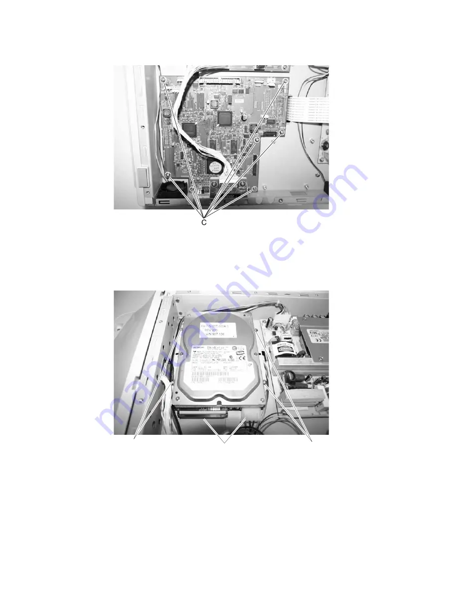
Remove the seven screws (C) securing the board.

Note:  Run registration if you are installing a new scanner control board. See 

“Configuration menu (CONFIG 

MENU)” on page 3-6

.

Hard disk drive assembly removal

Disconnect the two cables (A), and remove the four screws (B).

Note:  Run registration if you are installing a new hard disk drive. See 

“Configuration menu (CONFIG MENU)” 

on page 3-6

.

Note:  Customer date (forms, fonts, etc.) need to be reloaded on the hard disk drive.

A

B

B

Summary of Contents for 4036-307

Page 1: ...308 Table of contents Start diagnostics Safety and notices Trademarks Index Lexmark and Lexmark with diamond design are trademarks of Lexmark International Inc registered in the United States and or...

Page 2: ...ves appropriate without incurring any obligation to you References in this publication to products programs or services do not imply that the manufacturer intends to make these available in all countr...

Page 3: ...eed or skew 2 14 Image does not appear 2 14 Image unclear 2 15 Large jitter 2 15 Reading position deviation 2 15 Strange sound generated ADF 2 16 Strange sound generated flatbed 2 16 842 00 Scanner fa...

Page 4: ...Entering Configuration Menu 3 6 Available menus 3 6 Panel Menus 3 7 Format Fax Storage 3 7 ADF Edge Erase 3 7 FB Edge Erase 3 7 Automatic Scanner Registration 3 8 EVENT LOG 3 9 Jobs On Disk 3 9 Disk E...

Page 5: ...atbed CCD optical unit removal 4 30 Flatbed lamp assembly removal 4 32 Flatbed lamp inverter board removal 4 34 Bottom plate removal 4 35 Hard disk drive A1 board scanner control board power supply bo...

Page 6: ...vi Service Manual 4036 307 308 Assembly 4 Electronic boards 7 8 Assembly 5 Miscellaneous 7 10 Index I 1 Part number index I 3...

Page 7: ...r es Les consignes d entretien et de r paration de ce produit s adressent uniquement un personnel de maintenance qualifi Le d montage et l entretien de ce produit pouvant pr senter certains risques le...

Page 8: ...i n sobre el mantenimiento de este producto est dirigida exclusivamente al personal cualificado de mantenimiento Existe mayor riesgo de descarga el ctrica y de da os personales durante el desmontaje y...

Page 9: ...producte est orientada exclusivament a professionals i no est destinada a ning que no ho sigui El risc de xoc el ctric i de danys personals pot augmentar durant el proc s de desmuntatge i de servei d...

Page 10: ...ntify the connector locations and test points on the printer 6 Preventive maintenance contains the lubrication specifications and recommendations to prevent problems 7 Parts catalog contains illustrat...

Page 11: ...our time to read this manual thoroughly to obtain comprehensive knowledge about the scanner before servicing the unit Features Ease of use The control panel on the front of the scanner looks like a pa...

Page 12: ...A touch screen Image Types 42 bit color internal 14 bit gray internal 1 bit line art Dither Error Diffusion Scan Accuracy Flatbed ADF Leading Edge 1 2 mm 2 5 2 5 mm Side Edge 1 2 mm 2 5 2 5 mm Skew 1...

Page 13: ...olor Document Capacity 50 sheets Document Document size Max 8 5 x 14 inch W x L Min 4 5 x 5 5 inch W x L Thickness 0 05 0 15 mm ADF Automatic Document Feeder CCD Charge Couple Device CCFL Cold Cathode...

Page 14: ...1 4 Service Manual 4036 307 308...

Page 15: ...ther than an error message Symptom tables on page 2 2 Scan module does not move to home position on page 2 2 Reading is not performed on page 2 2 Image does not appear on page 2 2 Large jitter on page...

Page 16: ...tion Reading is not performed Scan module does not move to home position The power does not come on Go to The power does not come on on page 4 13 Display panel Go to Display panel remains blank on pag...

Page 17: ...is obtained 3 When the last screen displays the original message displays Printed error codes Additional codes are available in the Menus and Messages Guide for this option and the Service Manual for...

Page 18: ...Front scan module cable failure or SCC card failure CCD channel failure on page 4 19 845 01 Rear scan module cable failure or SCC card failure CCD channel failure Check each channel mono R G B for ide...

Page 19: ...dem Config ID Mismatch A device doesn t have a modem installed even though its Configuration ID indicates that a modem should be present See 848 00 Modem config ID mismatch on page 4 21 848 01 Modem C...

Page 20: ...ter the last successfully scanned page Touch Scan from flatbed if page jam recovery is active Scanning resumes from the flatbed immediately after the last successfully scanned page Touch Finish job wi...

Page 21: ...age Touch Finish job without further scanning if page jam recovery is active The job ends at the last successfully scanned page but the job is not canceled Successfully scanned pages go to their desti...

Page 22: ...essfully scanned pages go to their destination copy fax e mail or FTP Replace jammed originals if restarting job One or more messages that interrupted a scan job are now cleared Replace the original d...

Page 23: ...rt job if the job is restartable The message clears and a new scan job containing the same parameters as the previous job starts Scanner ADF Cover Open The scanner automatic document feed cover is ope...

Page 24: ...more memory Touch Cancel Job to cancel the current job if needed 38 Memory full The MFP is processing data but the memory used to store pages is full To avoid this error in the future Simplify the pr...

Page 25: ...t jam at the first paper feed sensor while the scanner is idle Clear the jam from the scanner to clear the message Either page or job recovery completes 291 00 Scanner jam remove all originals from th...

Page 26: ...scan job containing the same parameters as the previous job starts 294 00 Scanner jam remove all originals from the scanner The scanner detects a jam at the ADF second paper feed sensor Remove all ori...

Page 27: ...PCI card and printer scanner card seated properly in the printer Go to step 7 Reseat card s 7 Is the PS_RC signal at 5V on the PCI card Replace PCI card and printer scanner card assembly Replace PCI c...

Page 28: ...d board Done Step Action and Question Yes No 1 Is the paper correctly set in the tray Go to step 2 Properly position paper in document feeder 2 Is the specified paper used Go to step 3 Use correct fee...

Page 29: ...CCD assembly Step Action and Question Yes No 1 Are you placing the original on the flatbed Go to step 2 Go to step 3 2 Inspect the carriage transport belt Is the belt damaged Replace the carriage tra...

Page 30: ...r feed motor Replace the ADF unit Step Action and Question Yes No 1 Inspect the carriage transport belt Is the belt damaged Replace the carriage transport belt Go to step 2 2 Is the rail dirty Clean t...

Page 31: ...n Is either end of the cable loose Reseat flatbed motor cable Go to step 2 2 Does the flatbed motor cable have any visible damage Replace flatbed motor cable Replace flatbed optical unit Step Action a...

Page 32: ...flatbed CCD cable securely connected Replace flatbed optical unit Reset flatbed CCD cable Step Action and questions Yes No 1 Check the ADF lamp Is the lamp on brightly Go to step 3 Go to step 2 2 Is...

Page 33: ...th glass removal on page 4 28 for more information 2 Remove the bottom plate to expose the cable See Bottom plate removal on page 4 35 for more information Is the cable loose Reseat flatbed CCD cable...

Page 34: ...2 Remove the bottom plate to expose the cable See Bottom plate removal on page 4 35 for more information Replace the flatbed CCD data cable Reseat flatbed CCD data cable Step Action and questions Yes...

Page 35: ...check the back panel Replace the A1 board with 40X2179 Go to Step 2 2 Is modem cable securely connected to the back of the scanner Go to step 3 Reseat modem cable 3 Is the modem cable damaged Replace...

Page 36: ...nged from the application use the option control panel MarkVision Professional or the Embedded Web Server EWS pages Changing a setting from any of these makes that setting the user default Note Whenev...

Page 37: ...he home screen When in any other menu while the MFP is Ready it cancels all changes that have not been submitted and returns the MFP to the home screen Start Initiate the current job indicated on the...

Page 38: ...the Ready state The Menus button is on a gray bar called the navigation bar The bar contains other buttons described as follows Status message bar Shows the current MFP status such as Ready or Busy Sh...

Page 39: ...P 1 Touch Lock Device to open a PIN entry screen 2 Enter the correct PIN to lock the control panel which locks both the control panel buttons and the touch screen buttons Once the control panel is loc...

Page 40: ...int job copy job fax profile FTP e mail send Each heading has its own list of jobs shown in a column under it Each column can only show three jobs per screen Each job appears as a button If more than...

Page 41: ...ed On the gray navigation bar these two choices indicate that two types of scanning are possible One may choose to scan from the ADF or the flatbed Submit A green button indicates a choice If a differ...

Page 42: ...2 28 Service Manual 4036 307 308 Sample screen two...

Page 43: ...list appears on this screen Up arrow Touch the up arrow to move up to the next item in a list such as a list of menu items or values When on the first screen presented with a long list the up arrow is...

Page 44: ...Legal and a new screen appears 4 Touch Next and a new screen appears 5 Touch Plain Paper for the type of print media needed 6 Touch Continue The Copy screen returns to allow other selections besides C...

Page 45: ...from the screen Note The Back button appears on each menu screen except for the home screen Home Return to the home screen Note The Home button appears on every screen except the home screen For more...

Page 46: ...then the selection is not saved and it does not become the user default setting Attendance message alert If an attendance message occurs which closes a function such as copy or fax then a blinking re...

Page 47: ...u group consists of menus settings and operations that are used to diagnose various printer problems Note While the Diagnostics menu group is active all host interfaces are offline See Diagnostics Men...

Page 48: ...te For other items in the menu see the printer service manual Touch Exit Diag Menu to exit the Diagnostics Menu and Resetting the Printer displays The printer performs a POR and the printer returns to...

Page 49: ...To view the event log 1 Touch to select Display Log from EVENT LOG Up to three error codes display at a time Touch to display additional information if available 2 Touch Back to return to the EVENT LO...

Page 50: ...Test To run the Scanner Feed test 1 Touch to select Feed Test from the SCANNER TESTS menu 2 The panel displays the setting s current value setting s current value Use the arrows to select from Letter...

Page 51: ...ADF Jam Removal ADF Paper Present FB Cover Open Home Sensor SCAN_QRY_PAPER_SIZE_ADF_LONG SCAN_QRY_PAPER_SIZE_ADF_WIDTH1 SCAN_QRY_PAPER_SIZE_ADF_WIDTH2 SCAN_QRY_PAPER_SIZE_ADF_WIDTH3 SCAN_QRY_PAPER_SIZ...

Page 52: ...r performs a POR and the printer returns to normal mode Panel See Panel Menus on page 3 7 Format Fax Storage See Format Fax Storage on page 3 7 ADF Edge Erase See ADF Edge Erase on page 3 7 FB Edge Er...

Page 53: ...have a 2 mm no print border The larger of the 2 mm no print border and the Edge Erase setting will be used in this situation To change this setting 1 Touch to select ADF Edge Erase from the Configurat...

Page 54: ...stration from the Configuration Menu 3 Place a colored piece of paper in the ADF making sure the edge guides are properly adjusted Place another piece of paper A4 or letter on the flatbed Touch Start...

Page 55: ...OG Note An event log printed from the CONFIG MENU will not contain debug information or secondary codes for 900 service errors However the event log printed from DIAGNOSTICS mode does include this inf...

Page 56: ...f no advanced password exists you can establish one by using the keyboard that appears on the LCD 2 Touch next to either Enable or Disable If you remove an encrypted disk from a device and then try to...

Page 57: ...u with a tool for erasing the contents of a disk Warning Wipe Disk removes a disk s data in such a way that it cannot be recovered To change this setting 1 Touch to select Wipe Disk from Configuration...

Page 58: ...ating key will repeat The range is 1 100 with a default of 15 times per second To change this setting 1 Touch to select Key Repeat Initial Delay from the Configuration Menu 2 Touch to increase the val...

Page 59: ...ting The MFP prints a new copy of the page that jammed if Jam Recovery is set to On or Auto however the Auto setting does not guarantee the page will print Identifying jams If the MFP jams the appropr...

Page 60: ...ear the entire paper path to ensure you have cleared all possible jams Message What to do 290 xx through 294 xx Remove all original documents from the ADF Open the ADF cover and remove any jammed page...

Page 61: ...ning of the ADF cover exit Jams can also occur at the rear of the ADF paper path Note The following clearing jam instructions may seem out of numerical sequence However they have been grouped to help...

Page 62: ...3 16 Service Manual 4036 307 308...

Page 63: ...u need to put down the ESD sensitive part for any reason first put it into its special bag Machine covers and metal tables are electrical grounds They increase the risk of damage because they make a d...

Page 64: ...screws of parts that must not be disassembled These screws have a red coating 4 Store the disassembled parts in a clean place to avoid loss 5 After replacement check the contacts and spare part mount...

Page 65: ...ent input tray removal 1 Press down on the latches A on the top of the document input tray and tilt the document tray back 2 Disconnect the paper length connect cable B 3 Press the tabs C on the side...

Page 66: ...wer cover removal 1 Remove the document input tray See Document input tray removal on page 4 3 2 Remove the ADF upper cover See ADF upper cover removal on page 4 8 3 Remove the four screws A 4 Rotate...

Page 67: ...Repair information 4 5 4036 307 308 5 Disconnect the ground cable B 6 Remove the screw C and remove the ground wire B...

Page 68: ...4 6 Service Manual 4036 307 308 7 Disconnect the paper present paper feed cables D from the ADF sensor board 8 Remove the ADF lower cover...

Page 69: ...pen the ADF outer cover 2 Remove three screws B 3 Remove the ADF outer cover Installation note To reinstall the ADF outer cover close the ADF upper cover slide the ADF outer cover hinges C under the t...

Page 70: ...ve the ADF outer cover See ADF outer cover removal on page 4 7 2 Pivot the ADF upper cover to remove ADF lamp removal 1 Remove the paper feed assembly See Paper feed assembly removal on page 4 16 2 Tu...

Page 71: ...ion 4 9 4036 307 308 3 Remove the lamp cover B and set it aside 4 Note the position of the two leaf springs C on the right and left so you can replace them 5 Remove the two screws D 6 Remove the metal...

Page 72: ...307 308 7 Remove the lamp cable from the channel 8 Lift the lamp by the ceramic ends and remove Do not touch the glass Note Run registration if you are installing a new ADF lamp See Configuration menu...

Page 73: ...ADF motor distribution board removal 1 Remove document cover assembly See Document cover assembly removal on page 4 14 2 Remove the two screws A and remove the cover 3 Remove the four cables B 4 Remov...

Page 74: ...ng 1 Remove the ADF lower cover See ADF lower cover removal on page 4 4 2 Disconnect the three cables A 3 Remove the three screws B from the ADF optical unit 4 Remove the ADF optical unit Note Run reg...

Page 75: ...r removal on page 4 4 2 Disconnect the cables from the ADF motor sensor board 3 Remove the screw A 4 Remove the ADF sensor board ADF upper cover sensor removal 1 Remove the ADF lower cover See ADF low...

Page 76: ...e document input tray See Document input tray removal on page 4 3 2 Unplug the two cables A from the back of the flatbed scanner 3 Open the document cover assembly 4 Place a hand at the top of the lid...

Page 77: ...036 307 308 5 Pull the document cover assembly tabs up and out one at a time 6 Remove the document cover assembly Note Run registration if you are installing a new document cover See Configuration men...

Page 78: ...F optical unit removal on page 4 12 3 Remove the paper feed motor See Paper feed motor removal on page 4 17 4 Remove the ground wire screw A 5 Unplug the three cables B 6 Remove the four screws C 7 Li...

Page 79: ...4036 307 308 Paper feed motor removal 1 Remove the ADF lower cover See ADF lower cover removal on page 4 4 2 Remove the three screws A securing the paper feed motor 3 Disconnect the cable B 4 Remove t...

Page 80: ...ual 4036 307 308 Paper feed roller removal 1 Press the lever A to open the ADF outer cover 2 Push down on the latch B securing the paper feed roller 3 Remove the paper feed roller by freeing the right...

Page 81: ...sor removal 1 Remove the document input tray See Document input tray removal on page 4 3 2 Turn the document input tray over 3 Remove the five screws A on the document input tray inner cover 4 Disconn...

Page 82: ...rom the document input tray Paper present and paper feed 1 sensors removal 1 Remove the ADF lower cover See ADF lower cover removal on page 4 4 2 Remove the two screws A 3 Remove the paper present sen...

Page 83: ...d removal After scanning approximately 40 000 pages through the ADF the pick roll pad may be worn and you may experience problems with document feeding In this case replace the pick roll pad To remove...

Page 84: ...36 307 308 Scanner cushion removal 1 Remove the document cover assembly See Document cover assembly removal on page 4 14 2 Remove the two screws A and remove the cover 3 Remove the five screws B 4 Lif...

Page 85: ...d board removal 1 Remove the control panel assembly See Control panel assembly removal on page 4 24 2 Disconnect the three cables A from the keypad board 3 Remove the six screws B that secure the boar...

Page 86: ...Make sure the glass pane is placed on a soft clean surface to avoid scratching the glass 3 Remove the four screws A to loosen the control panel assembly from the scanner 4 Place the scanner right side...

Page 87: ...ove the screw B to disconnect the cable from the touch screen 6 Disconnect the cable C from the keypad board Keypad removal 1 Remove the control panel keypad board See Control panel keypad board remov...

Page 88: ...LCD HV inverter board removal 1 Remove the control panel assembly See Control panel assembly removal on page 4 24 2 Remove the two screws A and lift the metal cover 3 Remove the four screws B and dis...

Page 89: ...the control panel assembly See Control panel assembly removal on page 4 24 2 Disconnect the four cables A 3 Remove the six screws B 4 Turn the control panel assembly over carefully The bezel and displ...

Page 90: ...6 307 308 Flatbed cover with glass removal 1 Remove the control panel assembly See Control panel assembly removal on page 4 24 2 Remove the two screws A and two screws B 3 Lift straight up to remove t...

Page 91: ...CD optical unit See Flatbed CCD optical unit removal on page 4 30 2 Remove the screw A and lift the belt from the pin 3 Remove the clip B on the other end of the belt and remove it from the pin 4 Remo...

Page 92: ...ws with red coating 1 Remove the flatbed cover with glass See Flatbed cover with glass removal on page 4 28 2 Disconnect the two CCD cables A 3 Remove two screws B securing the strap and lift the meta...

Page 93: ...belt C from the flatbed optical CCD Note Take note of the belt routing within the optical unit 6 Remove the flatbed optical CCD Note Run registration if you are installing a new flatbed CCD optical u...

Page 94: ...mbly removal 1 Remove the flatbed cover with glass See Flatbed cover with glass removal on page 4 28 2 Remove the two screws A securing the flatbed optical CCD unit top cover and remove the cover 3 Di...

Page 95: ...Repair information 4 33 4036 307 308 5 Lift tabs D 6 Raise the lamp assembly to the highest position 7 Unclip the corner E of the cover closest to the control panel first 8 Remove the other side...

Page 96: ...lass See Flatbed cover with glass removal on page 4 28 2 Remove the two screws A securing the flatbed optical CCD unit upper cover and remove the cover 3 Disconnect the cables B 4 Remove the screw C h...

Page 97: ...moval 1 Remove the document cover assembly See Document cover assembly removal on page 4 14 2 Place the scanner on its back Note Make sure you place the glass on a clean soft surface to protect it 3 R...

Page 98: ...upply board and modem board removals 1 Remove the bottom plate See Bottom plate removal on page 4 35 2 Remove the component you want from within the MFD cage See the following pages for the removals C...

Page 99: ...Repair information 4 37 4036 307 308 Scanner control board removal 1 Disconnect the seven cables A 2 Remove the four standoffs B securing the connector A A B...

Page 100: ...ol board See Configuration menu CONFIG MENU on page 3 6 Hard disk drive assembly removal Disconnect the two cables A and remove the four screws B Note Run registration if you are installing a new hard...

Page 101: ...air information 4 39 4036 307 308 Modem board removal Disconnect the cable A and remove the four screws B Power supply board removal Disconnect the three cables A and remove the four screws B B A B B...

Page 102: ...4 40 Service Manual 4036 307 308 A1 board removal Disconnect the eight cables A and remove the four screws B Note Load the serial number B A B B...

Page 103: ...an removal 1 Remove the bottom plate See Bottom plate removal on page 4 35 2 Remove the four screws A from the fan you need to remove 3 Remove the cables from their retainers 4 Remove either fan from...

Page 104: ...e Flatbed cover with glass removal on page 4 28 2 Lift the document cover sensor board and remove the cable A C77X printer operator panel cover removal 1 Open the front door 2 Remove the two operator...

Page 105: ...n 4 43 4036 307 308 C78X printer operator panel cover removal Push up on the bottom two corners of the panel to remove Mono printer operator panel cover removal Push up on the bottom two corners of th...

Page 106: ...4 44 Service Manual 4036 307 308...

Page 107: ...ons This section contains an overview of the major components of the scanner hardware External view Automatic document feeder ADF Document input tray Document output tray Paper stop Control panel Powe...

Page 108: ...5 2 Service Manual 4036 307 308 Internal Components...

Page 109: ...CN 5 GND 6 MDC_RXD_CN 7 MDC_TXD_CN 8 GND 9 ADF_PAP_PRE S_CN 10 FB_COV_CLOSED_CN 11 GND 12 MDC_RST_NR J2 1 FB_LAMP_ON_R 2 FB_POWER_SAVER_R 3 24 V_LAMP_UI 4 24 V_LAMP_UI 5 24 V_LAMP_UI 6 FB_CCD_BW_SEL_R...

Page 110: ...30 GND 31 FBR_AFE_D1 32 FBR_AFE_D0 33 GND 34 FBR_AFE_SEN 35 FBR_AFE_SCK 36 FBR_AFE_SDI J7 1 12 V 2 GND 3 GND 4 5 V J13 1 5 V 2 GND 3 3 3 V 4 3 3 V 5 MOD_D0 6 MOD_D1 7 MOD_D2 8 MOD_D3 9 GND 10 MOD_D4 1...

Page 111: ...S J15 1 UI_RESET_NR 2 GND 3 TX1 4 TX1 5 TX2 6 TX2 7 CLKTX 8 CLKTX 9 GND 10 GND 11 RXD232_N 12 TXD232_N 13 TX0 14 TX0 15 GND 16 GND 17 24 V_LAMP_UI 18 24 V_LAMP_UI J28 1 ADF_LAMP_ON_R 2 ADF_POWER_SAVE_...

Page 112: ...ADFR_AFE_D7 22 ADFR_AFE_D6 23 GND 24 ADFR_AFE_D5 25 ADFR_AFE_D4 26 GND 27 ADFR_AFE_D3 28 ADFR_AFE_D2 29 GND 30 ADFR_AFE_D1 31 ADFR_AFE_D0 32 GND 33 ADFR_AFE_SEN 34 ADFR_AFE_SCK 35 ADFR_AFE_SDI 36 CCD...

Page 113: ...Connector locations 5 7 4036 307 308 J47 cont 11 GND 12 GND 13 GND 14 GND 15 GND 16 GND 17 GND 18 GND Scanner control board Conn ector Pin no Signal...

Page 114: ...V 2 GND 3 3 3 V 4 3 3 V 5 MOD_D0 6 MOD_D1 7 MOD_D2 8 MOD_D3 9 GND 10 MOD_D4 11 MOD_D5 12 MOD_D6 13 MOD_D7 14 GND 15 MOD_DA0 16 MOD_DA1 17 MOD_DA2 18 GND 19 MOD_DA3 20 MOD_DA4 21 MOD_DA5 22 GND 23 MOD...

Page 115: ...Connector locations 5 9 4036 307 308 Power supply board Connector Pin no Signal P1 1 GND 2 LIVE 3 NEUTRAL P2 1 24 V 2 GND 3 GND 4 24 V 5 OPEN 6 PS_RC 1 P2 P1 N L GND...

Page 116: ...GND 6 FBHMSR1 7 FBMEN 8 FBMRS 9 FBMS2 10 FBMS1 11 FBTQ2 12 FBTQ1 13 GND 14 FBSTEP 15 GND 16 GND J3 1 FAN_FEEDBACK 2 GND 3 FAN_POWER J4 1 SB_SNR0 2 FB_SNR1 3 FB_SNR 2 4 5 V_SENSOR 5 GND J5 1 MDC_DET_R...

Page 117: ...7 GND 8 XDATAP2 9 GND 10 XDATAP3 11 GND 12 XDATAP4 13 GND 14 GND 15 XDATAP5 16 GND 17 XDATAP6 18 GND 19 XDATAP7 20 GND 21 AM_RD1 22 AM_RD2 23 PAPER_OUT 24 AM_WRI 25 AMCLK 26 LOOP_OUT J8 1 FAN_FEEDBACK...

Page 118: ...5 12 Service Manual 4036 307 308...

Page 119: ...problems and maintain optimum performance Scheduled maintenance Customer replaceable parts Customer replaceable parts Part number Replacement life 4600 Separator roll pad 40X4755 Replace at approximat...

Page 120: ...6 2 Service Manual 4036 307 308...

Page 121: ...number 1 in the table Part number Identifies the unique number that identifies this FRU Units mach Refers to the number of units actually used in the base machine or product Units FRU Refers to the nu...

Page 122: ...7 2 Service Manual 4036 307 308 Assembly 1 ADF assembly...

Page 123: ...stop 11 40X2549 1 1 ADF sensor cable 6 pin 12 40X2543 1 1 ADF FF to motor distribution cable 13 40X2546 1 1 Paper feed motor cable 4 pin 14 40X2552 1 1 ADF motor distribution board 15 40X2534 1 1 Scan...

Page 124: ...7 4 Service Manual 4036 307 308 Assembly 2 Control panel 2 4 5 7 6 1 3...

Page 125: ...Asm Index Part number Units mach Units FRU Description 2 1 40X2593 1 1 Bezel 2 40X2556 1 1 Display panel assembly 3 40X2178 1 Keypad 4 40X2555 1 1 Keypad board 5 40X2558 1 1 FFC cable 6 40X2557 1 1 L...

Page 126: ...7 6 Service Manual 4036 307 308 Assembly 3 Lower scanner 1 2 4 3 5 6...

Page 127: ...r with glass 2 40X2564 1 1 Document cover sensor board 3 40X2562 1 1 Carriage transport belt includes Carriage transport belt Clip 4 40X2193 1 1 Flatbed CCD assembly includes Flatbed CCD assembly Flat...

Page 128: ...7 8 Service Manual 4036 307 308 Assembly 4 Electronic boards...

Page 129: ...modem model 308 only 8 40X2179 1 1 A1 board without modem model 307 only 9 40X2574 1 1 Modem to scanner control cable 30 pin model 308 only 10 40X2587 1 1 Document cover sensor cable 11 40X2578 1 1 A...

Page 130: ...S 40X4298 1 1 Mono printer scanner card assembly NS 40X2596 1 1 Mono printer operator panel cover NS 1 1 Screws parts packet P N 40X2589 NS 40X2199 1 Scanner registration kit NS 40X4278 1 1 C77X print...

Page 131: ...e 3 7 Key Repeat Rate 3 12 configuration menu accessing 3 1 3 6 available menus 3 6 Disk Encryption 3 10 EVENT LOG 3 9 Jobs On Disk 3 9 Panel Menus 3 7 control panel display removal 4 27 LCD 2 23 over...

Page 132: ...7 ADF sensor board 4 13 ADF upper cover 4 8 bottom plate 4 35 carriage transport belt 4 29 control cooling fan 4 41 control panel assembly 4 24 control panel display assembly 4 27 control panel keypa...

Page 133: ...e 7 3 40X2546 Paper feed motor cable 4 pin 7 3 40X2547 ADF paper feed motor 7 3 40X2548 ADF interface board 7 3 40X2549 ADF sensor cable 6 pin 7 3 40X2550 ADF CCD motor cable 10 pin 7 3 40X2551 ADF CC...

Page 134: ...7 3 40X2587 Document cover sensor cable 7 9 40X2588 Control panel ground cable 7 9 40X2589 Screws parts packet 7 10 40X2593 Bezel 7 5 40X2596 Mono printer operator panel cover 7 10 40X2597 C77X print...

Reviews: