background image


Leuze electronic GmbH + Co. KG 

In der Braike 1 D-73277 Owen

We reserve the right to make changes 

[email protected]  •  www.leuze.com 

Tel. +49 (0) 7021 573-0

02/2018 – 50134615-01 – 7/22 


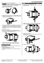
Hook the module onto the standard rail.  

Important! Make sure the shield spring is seated correctly. 

The module's shield springs must be securely attached to 

the standard rail and have a good electrical contact. 


Swivel the module onto the standard rail. 


Slide the latching foot against the standard rail with a 

screwdriver until the latching foot snaps into place with an 

audible CLICK. 


Make sure that the module is firmly mounted onto the 

standard rail. Try to remove the module from the standard 

rail with a little pressure. If the module remains firmly 

connected to the rail with this test, the mounting is correct. 


If multiple modules are mounted: 


Slide the individual modules together in the direction of the 

arrow until the lateral connector between the modules 

audibly snaps into place. 


Install an end terminal on the leftmost module and the 

rightmost module. 


4.1.2


After mounting 

After mounting the modules, the following steps are required: 


Electrically connect the modules. 


Configure the modules. 


Check installation before initial commissioning. 

4.2


Steps for removing the extension modules 


Disconnect the MSI 400 system from the power supply. 


Remove the plug-in block terminals with the wiring and the 

end terminals. 


Slide the modules apart separately in the direction of the 

arrow until the lateral connector is disconnected. 


Unlock the module. 

To do so, pull the module's latching foot outwards with a 

screwdriver. 


Swivel the module away from the standard rail. 


Summary of Contents for MSI-EM-IO84NP Series

Page 1: ... die sicherheitsgerichteten Ausgänge der Sicherheits Steuerung können die zugehörigen Aktoren der Maschinen oder Anlagen sicher abgeschaltet werden 2 3 Bestimmungsgemäße Verwendung Die modulare Sicherheits Steuerung MSI 400 darf nur inner halb spezifizierter Betriebsgrenzen Spannung Temperatur etc siehe dazu Abschnitt 6 Technische Daten verwendet werden Sie darf nur von fachkundigem Personal und n...

Page 2: ...1 Y4 IY5 IY8 Blinkt rot 2 Hz Kritischer Fehler Typ3 im System vermutlich in die sem Modul Die Anwen dung wurde gestoppt Leuchtet rot Kritischer Systemfehler 3 2 2 Anzeigen der Eingangs Ausgangs LEDs Eingang LED I1 I4 IY5 IY8 Ausgang LED Y1 Y4 IY5 IY8 Bedeutung Aus Ein Ausgang ist inaktiv Leuchtet grün Ein Ausgang ist aktiv Blinkt grün 1 Hz synchron mit der rot grünen MS LED Ausgang ist fehlerhaft ...

Page 3: ...er Schiene verbunden bleibt ist die Montage korrekt Wenn Sie mehrere Module montieren Schieben Sie die Module in Pfeilrichtung einzeln zusammen bis die seitliche Steckverbindung zwischen den Modulen hörbar einrastet Installieren Sie am äußerst linken Modul und am äußerst rechten Modul jeweils eine Endklammer 4 1 2 Nach der Montage Wenn Sie die Module montiert haben sind folgende Schritte notwendig...

Page 4: ...rgestellt werden dass der Systemstecker in das passende Hauptmodul gesteckt wird z B über Verdrahtung oder Markierung Weitere Informationen die bei Verwendung der Sicherheits Steuerung MSI 400 zu berücksichtigen sind finden Sie in den Betriebsanleitungen 6 Technische Daten Umgebungstempera tur im Betrieb 25 C 65 C Lagertemperatur 40 C 70 C Rel Luftfeuchtigkeit 10 95 nicht kondensierend Schwingfest...

Page 5: ...rol The corresponding actuators on the machine or systems can be securely switched off via the safety related outputs of the safety control 2 3 Intended use The modular safety control MSI 400 must only be used within specific operating limits voltage temperature etc see Section 6 Technical data It must only be used by expert personnel and only on the machine where it has been installed and initial...

Page 6: ... Flashes red 2 Hz Critical error type3 in the system probably in this module Application is stopped Lights up red Critical system error 3 2 2 Displays of input output LEDs Input LED I1 I4 IY5 IY8 Output LED Y1 Y4 IY5 IY8 Meaning Off Input output is inactive Lights up green Input output is active Flashes green 1 Hz synchronously with the red green MS LED Output is faulty A rectifiable error is pend...

Page 7: ...firmly connected to the rail with this test the mounting is correct If multiple modules are mounted Slide the individual modules together in the direction of the arrow until the lateral connector between the modules audibly snaps into place Install an end terminal on the leftmost module and the rightmost module 4 1 2 After mounting After mounting the modules the following steps are required Electr...

Page 8: ... module you must ensure that the system plug is plugged into the corresponding main module e g by wiring or marking The operating instructions contain more information that must be complied with when using the safety control system MSI 400 6 Technical data Ambient temperature during operation 25 C 65 C Storage temperature 40 C 70 C Relative Humidity 10 95 non condensing Vibration according 5 Hz 15...

Page 9: ...en toute sécurité via les sorties de sécurité de la commande de sécurité 2 3 Utilisation conforme à l usage prévu La commande de sécurité modulaire MSI 400 ne doit être utilisée que dans les limites d exploitation spécifiées tension température etc voir à ce sujet le paragraphe 6 Données techniques Elle doit être utilisée uniquement par du per sonnel qualifié et uniquement sur la machine sur laque...

Page 10: ...Y4 IY5 IY8 Clignote en rouge 2 Hz Erreur critique type3 en système probablement au cette module L application est arrêté Allumé en rouge Erreur de système critique 3 2 2 Affichage des LED d entrée sortie LED d entrée I1 I4 IY5 IY8 LED de sortie Y1 Y4 IY5 IY8 Signification Arrêt L entrée sortie est inactive Allumé en vert L entrée sortie est active Clignote en vert 1 Hz de manière synchrone avec le...

Page 11: ...e montage est correct Si vous montez plusieurs modules Poussez les modules individuels dans le sens de la flèche pour les regrouper jusqu à ce que la connexion latérale entre les modules s enclenche de manière audible Installez un clip d arrêt sur le module le plus à gauche et un sur celui le plus à droite 4 1 2 Après le montage Une fois les modules montés les étapes suivantes sont nécessaires Rac...

Page 12: ... trouverez de plus amples informations des points dont il faut tenir compte pour l utilisation de la commande de sécurité MSI 400 dans les modes d emploi 6 Données techniques Température am biante pendant le fonctionnement 25 C à 65 C Température de stockage 40 C à 70 C Humidité rel de l air 10 à 95 sans condensation Résistance aux efforts alternés 5 Hz 150 Hz EN 60068 2 6 Résistance aux chocs Cho...

Page 13: ...nza Attraverso le uscite di sicurezza della centralina è possibile spegnere in modo sicuro i relativi attuatori delle macchine o degli impianti 2 3 Utilizzo corretto La centralina di sicurezza modulare MSI 400 può essere usata solo entro i limiti operativi specificati tensione temperatura ecc a tale riguardo vedere il paragrafo 6 Dati tecnici Può essere utilizzata solo da personale esperto e solo ...

Page 14: ...rrore critico tipo3 nel si stema presunto in questo modulo Applicazione é ferma Rosso fisso Grave errore di sistema 3 2 2 Indicazioni dei LED ingressi uscite Ingresso LED I1 I4 IY5 IY8 uscita LED Y1 Y4 IY5 IY8 Significato Off Ingresso uscita non attivo a Verde fisso Ingresso uscita attivo a Verde lampeggiante 1 Hz in sincronia con MS LED rosso verde L uscita è difettosa È presente un errore rimovi...

Page 15: ...ante questo test il modulo rimane ben saldo sulla guida allora il montaggio è corretto Se si montano diversi moduli Spingere i moduli singolarmente nel verso della freccia fino a quando non si sente che il connettore a spina tra i moduli sia entrato Installare sui due moduli rispettivamente all estremità destra e all estremità sinistra una clip di arresto 4 1 2 Dopo il montaggio Una volta montati ...

Page 16: ...l modulo principale corretto ad es attraverso il cablaggio o la marcatura Ulteriori informazioni da considerare per l utilizzo della centralina di sicurezza MSI 400 sono disponibili nelle istruzioni per l uso 6 Dati tecnici Temperatura ambiente in esercizio 25 C 65 C Temperatura di immagazzinaggio 40 C 70 C Umidità rel dell aria 10 95 senza condensa Limite di fatica 5 Hz 150 Hz EN 60068 2 6 Resist...

Page 17: ...s posible desconectar con seguridad los actuadores correspondientes de las máquinas o instalaciones 2 3 Finalidad prevista Solo se permite utilizar el controlador de seguridad modular MSI 400 dentro de los límites de servicio especificados tensión temperatura etc véase al respecto la sección 6 Datos técnicos Solamente puede ser utilizado por personal especialista y solo en aquella máquina en la qu...

Page 18: ...e 2 Hz Fallo crítico tipo3 del sistema probablemente in este módulo La aplicación se ha detenido Rojo encendido Fallo crítico del sistema 3 2 2 Indicaciones de los LEDs de entrada salida LED de entrada I1 I4 IY5 IY8 LED de salida Y1 Y4 IY5 IY8 Significado Desconectado Entrada salida inactiva Verde encendido Entrada salida activa Verde intermitente 1 Hz sincronizado con el LED MS rojo verde La sali...

Page 19: ...e unido fijo con el raíl significa que el montaje es correcto Si monta varios módulos Junte uno a uno los módulos desplazándolos en la dirección de la flecha hasta que el conector lateral entre los módulos encastre de forma audible Instale una brida final junto al último módulo de la izquierda y otra junto al último módulo de la derecha 4 1 2 Después del montaje Cuando haya montado los módulos ser...

Page 20: ...sario asegurarse de que el conector del sistema está enchufado en el módulo principal adecuado p ej mediante el cableado o una marca Para obtener más información relevante para el uso del controlador de seguridad MSI 400 consulte las instrucciones de servicio 6 Datos técnicos Temperatura am biente durante el ser vicio 25 C 65 C Temperatura de al macenamiento 40 C 70 C Humedad relativa del aire 10 ...

Page 21: ...Leuze electronic GmbH Co KG In der Braike 1 D 73277 Owen We reserve the right to make changes info leuze de www leuze com Tel 49 0 7021 573 0 02 2018 50134615 01 21 22 ...

Page 22: ...Leuze electronic GmbH Co KG In der Braike 1 D 73277 Owen We reserve the right to make changes info leuze de www leuze com Tel 49 0 7021 573 0 02 2018 50134615 01 22 22 ...

Reviews: