


Device description
Leuze electronic
BCL 600i/BCL 601i
14
The additional USB interface is used for configuring the device.
The two product series BCL 600i and BCL 601i differ in their interfaces and in their function as multiNet
plus master or slave.
Table 3.1:
BCL 600i/BCL 601i interfaces
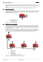
For the locations of the individual device connections, please refer to the device detail shown below.
1
Service, USB socket, type A
2
SW IN/OUT, M 12 socket (A-coded)
3
Bus OUT, M 12 socket (D-coded)
4
HOST/BUS IN, M 12 socket (D-coded)
5
PWR, M 12 connector (A-coded)
Figure 3.3: Location of the electrical connections
3.5
Display elements
3.5.1 Structure of the control panel
1
PWR LED
2
NET LED
3
Navigation buttons
4
Escape button
5
Enter button
6
Display
Figure 3.4: Structure of the control panel
HOST / BUS IN
BUS OUT
BCL 600i
(Stand alone or multiNet plus Master)
RS 232 / RS 422
RS 485
BCL 601i
(multiNet plus slave)
RS 485
RS 485
3
4
5
2
1
3
2
1
4
5
6


