Lenze i500 Series Operating Instructions Manual Download Page 17

17

Commissioning

Operating instructions I510-Cabinet

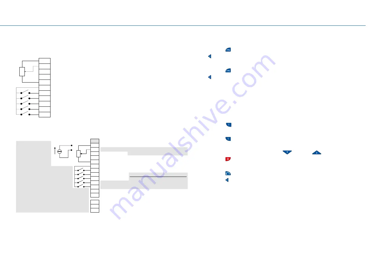
With the wiring shown below, the inverter can be operated using the control terminals (X3).

•  Preset 1 is activated if DI4 = HIGH.
•  Preset 2 is activated if DI5 = HIGH.
•  Preset 3 is activated if DI4 and DI = HIGH.

GND

AI1
AI2

AO1
10V
24V

DI1
DI2
DI3
DI4
DI5

Setpoint frequency

10 VDC supply
24 VDC, 100 mA supply
Start
Reset error  (optional)


Change direction of rotation  (optional)

Activate preset  (Bit 0) (optional)
Activate preset  (Bit 1) (optional)

GND

Input range [Hz]:

*P430.02 - *P430.03

7.1.4 

Extended terminal control

The following illustration shows a more extensive wiring of the control terminals (X3) linked 

with the respective parameters.

GND

AI1
AI2

AO1
10V
24V

DI1
DI2
DI3
DI4
DI5

GND

DO1

NO

COM

NC

U/I

*P400.02

Preset 01 (*P450.01)

*P400.04
*P400.13

bit 1 bit 0

0

0

1

1

1

1

Preset 02 (*P450.02)

Preset 03 (*P450.03)

*P400.18
*P400.19
*P420.02

*P420.01

24E

*P201.01
(congured AI1 as 
standard setpoint)

Default setting

Start

Reset error

Mark direction of rotation

Activate preset (bit 0)
Activate preset (bit 1)

DO1 activated at

Release brake

Relay activated at

Ready for operation

Analog input 1
Analog input 2
Analog output 1

10 VDC supply for potentiometer
24 VDC, 100 mA supply, reference for digital inputs
Digital input 1
Digital input 2
Digital input 3
Digital input 4
Digital input 5
Digital output 1
GND for analog and digital signals

Relay NO contact
Relay common contact
Relay NC contact

Preset frequency values

*P430.01 

(0 ... 10 VDC signal)

*P430.02 — *P430.03

GND for analog and digital signals

range [Hz]:

cong.:

Optional external 24-V-supply (i550 only)

7.2  Keypad control

Activate temporary keypad control

1.  Press the key   to activate keypad control.
2.  Key   for confirming keypad control.

Deactivate temporary keypad control

1.  Press the key   to activate keypad control.
2.  Key   for confirming keypad control.

Activate permanent keypad control

If the keypad does not have any keys, motor control is activated via the following parameters:


Set parameter P200.00 to 1.


Set parameter P201.01 to 1.


Set parameter P400.01 to 1.


Set parameter P400.02 to 1.

Then use the key   to start the motor.

Start/control/stop motor with keypad

1.  Press the key   to start the motor.

•  The keypad shows the motor speed.

2.  Change the frequency setpoint using the key 

 or the key 

.

3.  Press the key   to stop the motor.

Change rotating direction

1.  Press the key  .
2.  Press the key   to confirm the reversal of rotating direction.

7.3  Commissioning with the EASY Starter

Commissioning and diagnostics can be carried out with the EASY starter engineering tool. 

http://www.Lenze.com

Summary of Contents for i500 Series

Page 1: ...Inverter Inverter i510 Cabinet 0 25 15 kW Operating Instructions EN As easy as that ...

Page 2: ...ns connec on DC bus Relay output Network Interface Control terminals Shielding of control connec ons IT screw IT screw from 0 55 kW Inverter status s LED Motor connec on Op on Op on Basic I O Diagnos c module Brake resistor connec on Memory module Netword status s LED Toggle switch CANopen Modbus X100 X16 X3 X20 X105 X216 X9 ...

Page 3: ... 9 5 3 Control terminals 10 5 4 Relay output 10 5 5 Single phase mains connection 230 240 V 11 5 6 Three phase mains connection 230 240 V 12 5 7 Three phase mains connection 400 V 13 5 8 Three phase mains connection 480 V 14 6 Initial switch on 15 7 Commissioning 15 7 1 Keypad module 15 7 1 1 Functions of the keys 16 7 1 2 Example of the keypad handling 16 7 1 3 Quick commissioning terminal contro...

Page 4: ...r the power range of 0 25 15 kW The inverter i510 is suitable for conveyor and travelling drives pumps fans winders lifting systems and many other machine tasks The inverter is not to be used as a household appliance but for commercial or professional purposes only The inverter is not a machine in terms of the Machinery Directive 1 3 Device specific standards and directives The product meets the p...

Page 5: ... to severe personal injury and damage to property The product must only be used as directed must never be commissioned if they display signs of damage must never be technically modified must never be commissioned if they are not fully mounted must never be operated without required covers must only be disconnected from the installation in de energized condition Connect disconnect all pluggable ter...

Page 6: ... user must take the residual hazards mentioned into consideration in the risk assessment for his her machine system If the above is disregarded this may result in injuries to persons and material damage Product Observe the warning labels on the product Icon Description Electrostatic charges Before working on the product the staff must ensure they are free of any electrostatic charges Electrical vo...

Page 7: ...bove this 300 mA Operation with earth leakage circuit breaker 400 V mains Up to 2 2 kW 30 mA above this 300 mA Cable length for EMC Category C2 Max 20 m 0 37 kW max 15 m Category C3 Max 35 m 0 37 kW max 15 m Switching frequencies 2 4 8 16 kHz the rated output currents apply at 45 C and switching frequencies of 2 and 4 kHz and at 40 C and switching frequencies of 8 and 16 kHz Ambient temperature 55...

Page 8: ... 260 1 M5 50 50 1 3 phase mains connection 230 240 V without integrated RFI filter I51AExxxD 0 25 0 37 0 75 155 60 130 165 1 M5 50 50 I51AExxxD 0 55 0 75 0 95 180 60 130 190 1 M5 50 50 I51AExxxD 1 1 2 2 1 35 250 60 130 260 1 M5 50 50 I51AExxxC 4 0 5 5 2 1 250 90 130 260 2 30 M5 50 100 Three phase mains connection 400 V 480 V Heavy duty with integrated RFI filter I51AExxxF 0 37 0 75 155 60 130 165 ...

Page 9: ...inet must support the EMC compliant installation with shielded motor cables Please use sufficiently conductive shield connections Connect the housing with shielding effect to the grounded mounting plate with a surface as large as possible e g of inverters and RFI filters Use central earthing points The following figure shows an example of effective wiring with shielding on the control cabinet wall...

Page 10: ... Reference potential GND Connection system Plug in spring terminal Inverter kW 0 25 15 Connection Control terminals X3 Connection type Plug in spring terminal Max cable cross section mm 1 5 Stripping length mm 9 Tightening torque Nm Tools required 0 4 x 2 5 Control terminals 5 4 Relay output The relay is not suitable for direct switching of an electromechanical holding brake Use a corresponding su...

Page 11: ...rter kW 0 25 0 37 0 55 0 75 1 1 1 5 2 2 Rated output current A 1 7 2 4 3 2 4 2 6 7 9 6 Max output current 15s A 2 6 3 6 4 8 6 3 9 10 5 14 4 Operation without mains choke Fuse Characteristic gG gL or gRL Max rated current A 10 10 16 16 25 25 25 Circuit breaker Characteristic B Max rated current A 10 10 16 16 25 25 25 Earth leakage circuit breaker 1 phase mains connection 30 mA type A or B Mains con...

Page 12: ...7 2 4 3 2 4 2 6 7 9 6 16 5 23 Max output current 15s A 2 6 3 6 4 8 6 3 9 10 5 14 4 24 8 34 5 Rated output current light duty A 20 6 27 6 Max output current 15s A 33 46 Operation without mains choke Fuse Characteristic gG gL or gRL Max rated current A 10 10 16 16 25 25 25 32 32 Circuit breaker Characteristic B Max rated current A 10 10 16 16 25 25 25 32 32 Operation with mains choke Fuse Characteri...

Page 13: ...kW 0 37 0 55 0 75 1 1 1 5 2 2 3 4 5 5 7 5 11 15 Rated output current heavy duty A 1 3 1 8 2 4 3 2 3 9 5 6 7 3 9 5 13 16 5 23 3 Max Output current 15 s A 2 6 3 6 4 8 6 4 7 8 11 2 14 6 19 26 33 47 Rated output current light duty A 8 8 11 9 15 6 23 28 2 Max Output current 15 s A 14 6 19 26 33 47 Operation without mains choke Fuse Characteristic gG gL or gRL Max rated current A 10 10 10 16 16 16 25 25...

Page 14: ... 2 3 4 5 5 7 5 11 15 Rated output current heavy duty A 1 1 1 6 2 1 3 3 5 4 8 6 3 8 2 11 14 21 Max Output current 15 s A 2 2 3 2 4 2 6 7 9 6 12 6 16 4 22 28 42 Rated output current light duty A 7 6 9 8 13 2 18 3 25 2 Max Output current 15 s A 12 6 16 4 22 28 42 Operation without mains choke Fuse Characteristic gG gL or gRL Max rated current A 10 10 10 16 16 16 25 25 25 32 32 Circuit breaker Charact...

Page 15: ...h on DANGER Electrical voltage Incorrect wiring can cause unexpected states during the commissioning phase Wiring must be complete and correct Check the wiring to ensure that it is free of short circuits and earth faults Adapt the motor circuit configuration star delta to the inverter Connect the motor in the correct phase relation rotating direction Check the Emergency off function of the overall...

Page 16: ...d hold the key for longer than 3 seconds to save the settings 7 1 1 Functions of the keys Key Actuation Action Press briefly Navigate in the Menu Change parameters Press briefly Go to Menu Parameters Confirm parameters Press and hold for 3s Save parameters P SAVED in the display indicates that the parameters have been saved Press briefly Quit Menu Parameters Press briefly Activate keypad control P...

Page 17: ...meter 24 VDC 100 mA supply reference for digital inputs Digital input 1 Digital input 2 Digital input 3 Digital input 4 Digital input 5 Digital output 1 GND for analog and digital signals Relay NO contact Relay common contact Relay NC contact Preset frequency values P430 01 0 10 VDC signal P430 02 P430 03 GND for analog and digital signals range Hz con g Optional external 24 V supply i550 only 7 2...

Page 18: ... direction commands with digital signal sources Keypad 1 This selection enables the motor to start exclusively via the start key of the keypad Other signal sources for starting the motor are ignored P201 01 F setp source Keypad 1 The setpoint is specified locally by the keypad Analog input 1 2 The setpoint is defined as analog signal via the analog input 1 Analog input 2 3 The setpoint is defined ...

Page 19: ...rs P327 04 and P327 05 for this purpose V f characteristic control VFC open loop 6 This control mode is used for the speed control of an asynchronous motor via a V f characteristic and is the simplest control mode P302 00 V f characteristic shape Linear 0 Linear characteristic for drives with constant load torque over the speed Square law 1 Square law characteristic for drives with a square law lo...

Page 20: ... Trigger FALSE Deactivate quick stop P400 04 Error reset Digital input 2 12 Assignment of a trigger to the Reset error function Trigger FALSE TRUE edge The active error is reset acknowledged if the error condition is no longer active and the error is resettable Trigger FALSE No action P400 05 DC braking Not connected 0 Assignment of a trigger to the Activate DC braking function Trigger TRUE Activa...

Page 21: ...for operation no error active no STO active and DC bus voltage ok Otherwise FALSE Operation enabled 52 TRUE if inverter and start are enabled Otherwise FALSE Stop active 53 TRUE if inverter is enabled and motor is not started and output frequency 0 Error active 56 TRUE if error is active Otherwise FALSE Device warning active 58 TRUE if warning is active Otherwise FALSE P420 02 DO1 function Release...

Page 22: ...activated the motor is brought to a standstill within the deceleration time set here The set deceleration time refers to the period of deceleration from the set maximum frequency P211 00 to standstill In the case of a lower actual frequency the actual deceleration time is reduced accordingly Setting is not effective in operating mode P301 00 CiA Velocity mode 7 4 3 Group 3 Motor control Display co...

Page 23: ...verter firmware All parameter changes made by the user are lost during this process This process may take some seconds When the device command has been executed successfully the value 0 is shown Loading parameters has a direct effect on cyclic communication The data exchange for control is interrupted and a communication error is generated P700 03 Device commands Save user data Off ready 0 Only st...

Page 24: ...t using the key if the cause of the error has been eliminated and no blocking time is active Press the key to reset the error The motor is stopped Press the key to revoke the stop Reset error via terminal control When terminal control is used errors can be reset in 2 ways 1 Via start signal P400 02 default setting of digital input 1 Cause of error has been eliminated and no blocking time is active...

Page 25: ...P324 00 In case of high mass inertias reduce maximum overload current of the inverter P324 00 to 150 3 Yes 2383 Warning Device utilisation Ixt too high Warning Check drive dimensions 0 Yes 3120 Mains phase fault Error Check mains connection wiring Check fuses 0 Yes 3210 DC bus overvoltage Error Reduce dynamic performance of the load profile Check mains voltage Check settings for brake energy manag...

Page 26: ... 6280 Trigger functions connected incorrectly Trouble Check and correct the assignment of the triggers to the functions When keypad or network control is active the two functions Inverter enable P400 01 and Run P400 02 can also be set to Constant TRUE 1 to start the motor 0 Yes 7180 Motor overcurrent Error Check motor load Check drive dimensions Adapt set warning threshold or error threshold to P3...

Page 27: ...ng and ordering the product Commissioning document Fundamental information for the installation and commissioning of the pro duct Mounting instructions Fundamental information on mounting the product The documents can be found in the Lenze Doc Finder 10 Disposal If pollutants are disposed off improperly they may cause a lasting damage to human health and the environment Thus electrical and electro...

Page 28: ... Strasse 3 32699 Extertal Germany HR Lemgo B 6478 Tel 49 5154 82 0 Fax 49 5154 82 2800 Email Sales de Lenze com Web www Lenze com Lenze Service GmbH Breslauer Strasse 3 32699 Extertal Germany Tel 0080002446877 24 h helpline Fax 49 5154 82 1112 Email Service de Lenze com ...

Reviews: