

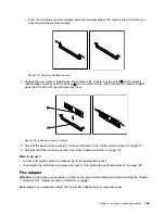
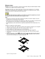


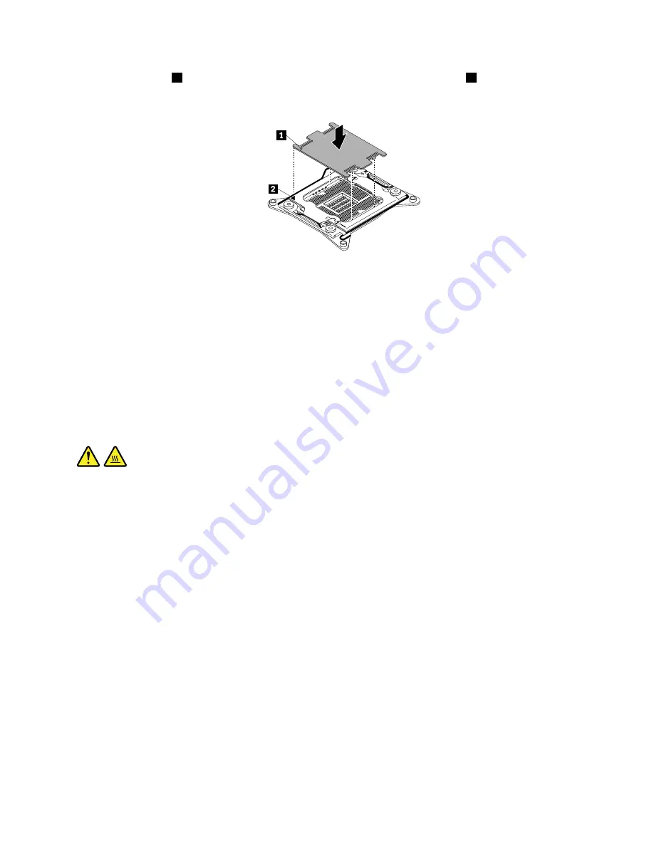
3. Align the notch
1
of the microprocessor socket cover with the alignment key
2
of the microprocessor
socket. Lower the socket cover straight down into the microprocessor socket on the system board.
Figure 137. Installing the microprocessor socket cover
Note:
Your microprocessor socket and cover might look slightly different from the illustration.
What to do next:
• To work with another piece of hardware, go to the appropriate section.
• To complete the installation or replacement, go to “Completing the parts replacement” on page 189.
Front panel I/O cable
Attention:
Do not open your computer or attempt any repair before reading and understanding the Chapter
1 “Read this first: Important safety information” on page 1.
CAUTION:
The heat sink and microprocessor might be very hot. Before you open the computer cover, turn off
the computer and wait several minutes until the computer is cool.
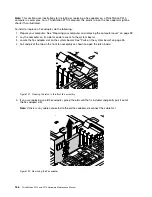
To remove the front panel I/O cable, do the following:
1. Prepare your computer. See “Preparing your computer and removing the computer cover” on page 99.
2. Remove the direct cooling air baffle. See “Direct cooling air baffle” on page 101.
3. Lay the computer on its side for easier access to the system board.
4. Remove all PCI or PCI Express cards that are installed. See “PCI card” on page 149 or “Full-length
5. Remove the optical-drive bracket. See “Optical-drive bracket” on page 122.
6. Remove the flex adapter if it is installed. See “Flex adapter” on page 165.
7. Remove the front fan assembly. See “Front fan assembly” on page 126.
8. Remove any rear fan assembly that is installed. See “Rear fan assembly” on page 159.
9. Remove the power supply assembly. See “Power supply assembly” on page 147.
10. Remove the memory modules that are installed. See “Memory module” on page 163.
11. Remove any heat sink and fan assembly that is installed. See “Heat sink and fan assembly” on page 161.
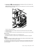
12. Record the cable routing and cable connections, and then disconnect all cables from the system board.
See “Parts on the system board” on page 35.
.
Installing or replacing hardware
177
Summary of Contents for ThinkStation P710
Page 1: ...ThinkStation P510 and P710 Hardware Maintenance Manual Machine Types 30B4 30B5 30B6 and 30B7 ...
Page 14: ...8 ThinkStation P510 and P710 Hardware Maintenance Manual ...
Page 18: ...12 ThinkStation P510 and P710 Hardware Maintenance Manual ...
Page 19: ...1 2 Chapter 1 Read this first Important safety information 13 ...
Page 20: ...1 2 14 ThinkStation P510 and P710 Hardware Maintenance Manual ...
Page 25: ...1 2 Chapter 1 Read this first Important safety information 19 ...
Page 26: ...1 2 20 ThinkStation P510 and P710 Hardware Maintenance Manual ...
Page 29: ...Chapter 1 Read this first Important safety information 23 ...
Page 40: ...Figure 5 Major FRUs and CRUs 34 ThinkStation P510 and P710 Hardware Maintenance Manual ...
Page 64: ...58 ThinkStation P510 and P710 Hardware Maintenance Manual ...
Page 70: ...64 ThinkStation P510 and P710 Hardware Maintenance Manual ...
Page 96: ...90 ThinkStation P510 and P710 Hardware Maintenance Manual ...
Page 104: ...98 ThinkStation P510 and P710 Hardware Maintenance Manual ...
Page 198: ...192 ThinkStation P510 and P710 Hardware Maintenance Manual ...
Page 202: ...196 ThinkStation P510 and P710 Hardware Maintenance Manual ...
Page 204: ...198 ThinkStation P510 and P710 Hardware Maintenance Manual ...
Page 208: ...202 ThinkStation P510 and P710 Hardware Maintenance Manual ...
Page 212: ...206 ThinkStation P510 and P710 Hardware Maintenance Manual ...
Page 216: ...210 ThinkStation P510 and P710 Hardware Maintenance Manual ...
Page 219: ......
Page 220: ......


