


1
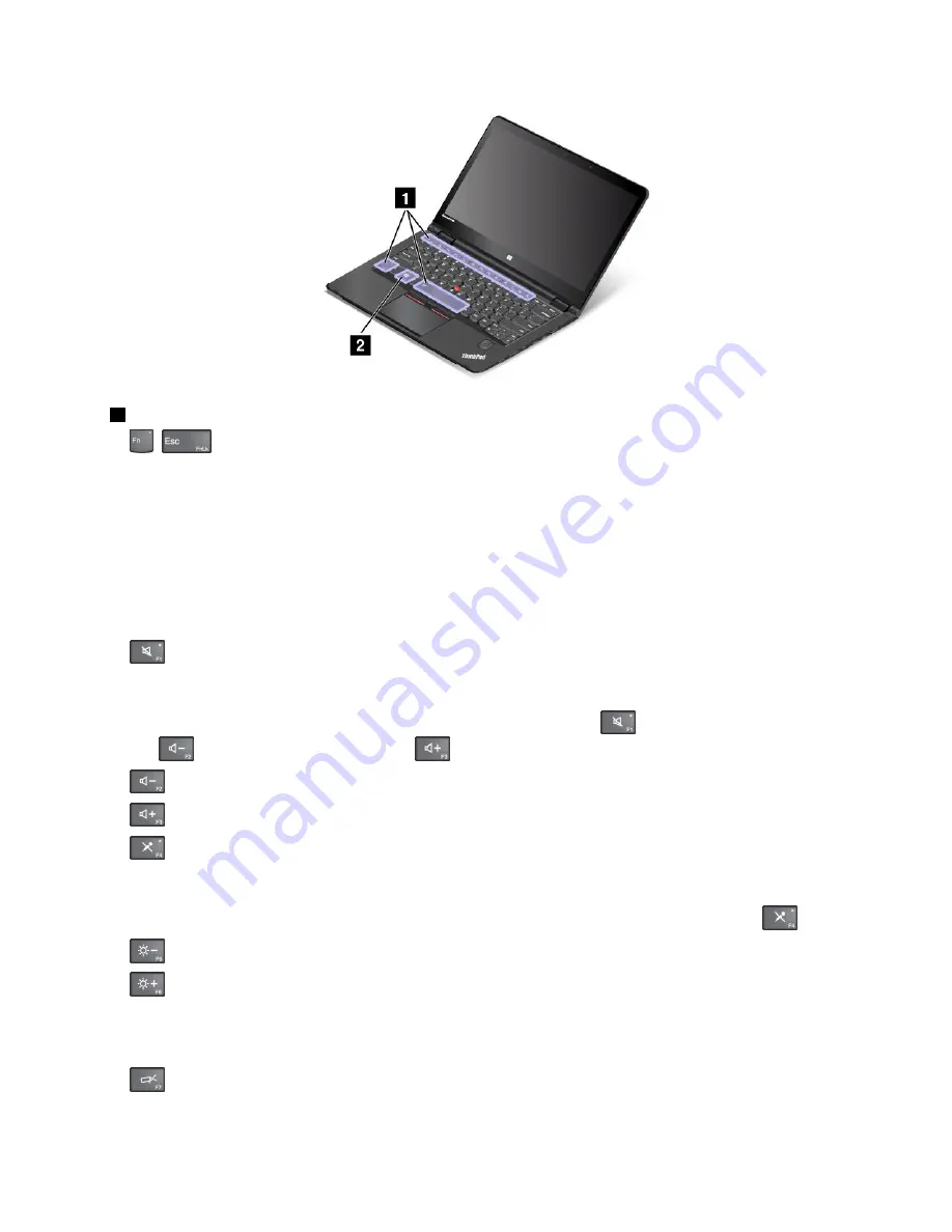
Function keys
•
+
: Press Fn+Esc to disable or enable the Fn Lock function.
When the Fn Lock function is disabled
: The Fn Lock indicator is off (default mode). To initiate the
special function printed as an icon on each key, press the function key directly. To input F1-F12, press
the Fn key and the corresponding function key.
When the Fn Lock function is enabled
: The Fn Lock indicator turns on. To input F1-F12, press the
function keys directly. To initiate the special function printed as an icon on each key, press the Fn key
and the corresponding function key.
Note:
Alternatively, you also can disable or enable the Fn lock function in the Keyboard Properties
window. See “Personalized keyboard” on page 64.
•
: Mutes or unmutes the speakers. When the speakers are muted, the speaker-mute indicator turns
on.
If you mute the sound and turn off your computer, the sound will remain muted when you turn on your
computer again. To turn on the sound, press the speaker mute key
, the speaker volume-down
key
, or the speaker volume-up key
.
•
: Decreases the speaker volume.
•
: Increases the speaker volume.
•
: Mutes or unmutes the microphones. When the microphones are muted, the microphone-mute
indicator turns on.
If you mute the microphones and turn off your computer, the microphones will remain muted when you
turn on your computer again. To unmute the microphones, press the microphone mute key
.
•
: Darkens the display.
•
: Brightens the display.
You can temporarily change the computer display brightness by pressing the two keys. To change the
default brightness level, right-click the battery-status icon in the Windows notification area. Then click
Adjust screen brightness
and make changes as desired.
•
: Switches the display output location between the computer display and an external monitor.
Note:
You also can press P to switch between the computer display and an external monitor.
Chapter 2
.
Using your computer
35
Summary of Contents for ThinkPad Yoga 14
Page 1: ...User Guide ThinkPad Yoga 14 ...
Page 6: ...iv User Guide ...
Page 16: ...xiv User Guide ...
Page 70: ...54 User Guide ...
Page 82: ...66 User Guide ...
Page 114: ...98 User Guide ...
Page 154: ...8 Install the new card in place 9 Install the dc in bracket in place 138 User Guide ...
Page 156: ...4 Detach the connector 5 Remove the screws Then remove the speaker assembly 140 User Guide ...
Page 160: ...144 User Guide ...
Page 164: ...148 User Guide ...
Page 170: ...154 User Guide ...
Page 174: ...158 User Guide ...
Page 178: ...162 User Guide ...
Page 183: ......
Page 184: ......


