


9. Remove the serial connector module. See “Replacing the serial connector module” on page 110.
10. Record the cable routing and cable connections, and then disconnect all cables from the system board.
See “Parts on the system board” on page 35.
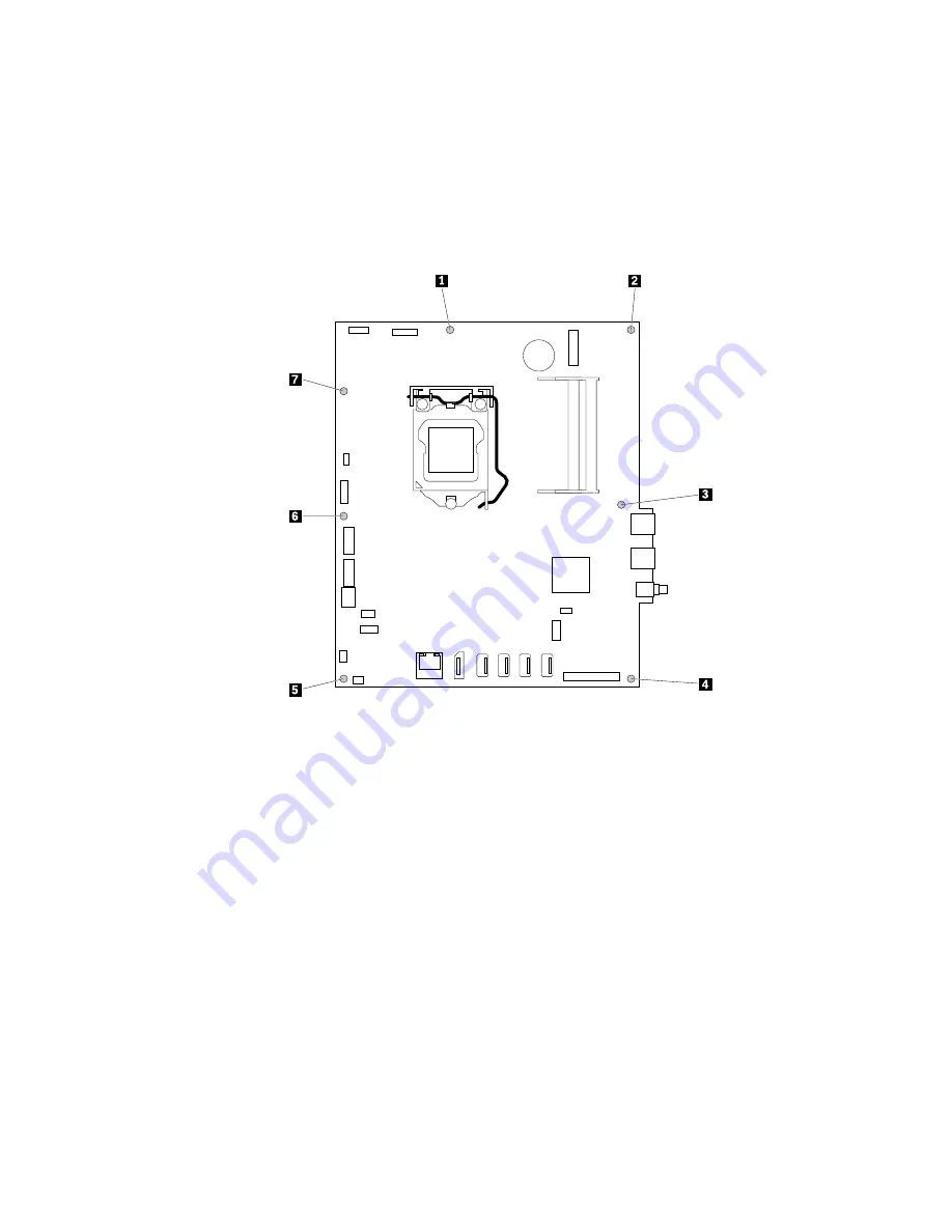
11. Remove the seven screws that secure the system board, and then carefully lift the system board out of
the chassis.
Note:
Carefully handle the system board by its edges.
Figure 50. Removing the system board
12. Remove the microprocessor from the failing system board, and then install it onto the new system
board. See “Replacing the microprocessor” on page 114.
13. Align the seven holes in the new system board with the corresponding screw holes in the chassis. Then,
install the seven screws to secure the system board.
14. Route all the cables that you disconnected from the failing system board, and then connect the cables
to the new system board. See “Parts on the system board” on page 35.
15. Reinstall the serial connector module. See “Replacing the serial connector module” on page 110.
16. Reinstall the card reader. See “Replacing the card reader” on page 110.
17. Reinstall the heat sink. See “Replacing the heat sink” on page 111.
18. Reinstall the memory modules. See “Replacing a memory module” on page 92.
19. Reinstall the Wi-Fi card. See “Replacing the Wi-Fi card” on page 107.
20. Reinstall the system board shield. See “Replacing the system board shield” on page 98.
21. Reinstall the computer cover. See “Replacing the computer cover” on page 95.
22. Reinstall the back cover and reconnect cables to your computer. See “Completing the parts
The failing system board must be returned with a microprocessor socket cover to protect the pins during
shipping and handling.
.
Installing or replacing hardware
113
Summary of Contents for ThinkCentre M900z 10F2
Page 1: ...ThinkCentre M900z Hardware Maintenance Manual Machine Types 10F2 10F3 10F4 and 10F5 ...
Page 6: ...iv ThinkCentre M900z Hardware Maintenance Manual ...
Page 8: ...vi ThinkCentre M900z Hardware Maintenance Manual ...
Page 16: ...8 ThinkCentre M900z Hardware Maintenance Manual ...
Page 20: ...12 ThinkCentre M900z Hardware Maintenance Manual ...
Page 21: ...1 2 Chapter 1 Read this first Important safety information 13 ...
Page 22: ...1 2 14 ThinkCentre M900z Hardware Maintenance Manual ...
Page 27: ...1 2 Chapter 1 Read this first Important safety information 19 ...
Page 28: ...1 2 20 ThinkCentre M900z Hardware Maintenance Manual ...
Page 31: ...Chapter 1 Read this first Important safety information 23 ...
Page 40: ...31 32 ThinkCentre M900z Hardware Maintenance Manual ...
Page 50: ...42 ThinkCentre M900z Hardware Maintenance Manual ...
Page 66: ...58 ThinkCentre M900z Hardware Maintenance Manual ...
Page 128: ...120 ThinkCentre M900z Hardware Maintenance Manual ...
Page 136: ...128 ThinkCentre M900z Hardware Maintenance Manual ...
Page 138: ...China RoHS 130 ThinkCentre M900z Hardware Maintenance Manual ...
Page 139: ...Appendix D China Energy Label Copyright Lenovo 2015 131 ...
Page 140: ...132 ThinkCentre M900z Hardware Maintenance Manual ...
Page 142: ...134 ThinkCentre M900z Hardware Maintenance Manual ...
Page 145: ......
Page 146: ......