Lenovo ThinkCentre M900z 10F2 Hardware Maintenance Manual Download Page 99

3. Place a soft, clean towel or cloth on the desk or surface. Hold the sides of your computer and gently lay

it down so that the screen is against the surface and the computer cover is facing up.

4. Remove the computer stand. See “Replacing the computer stand” on page 88.

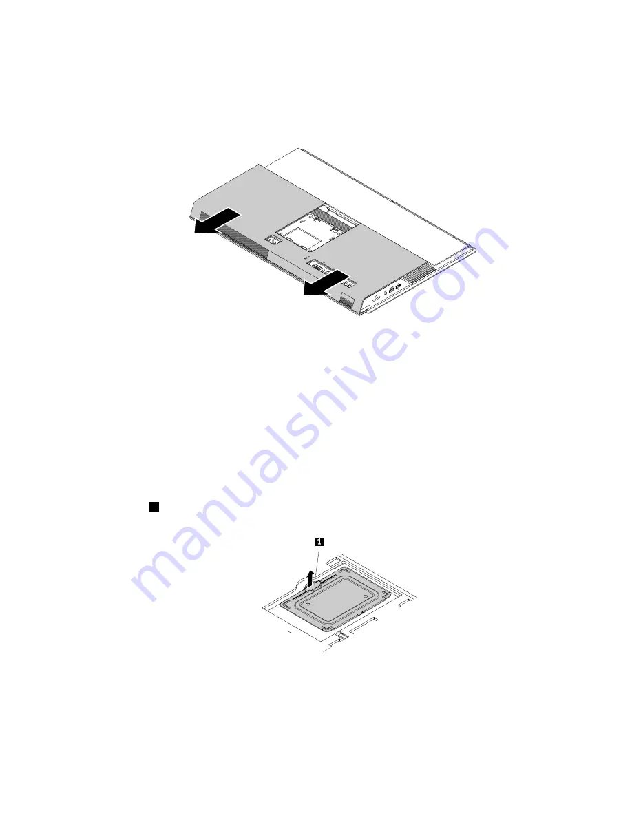
5. Slide the back cover as shown to remove it from the chassis.

Figure 20. Removing the back cover

Replacing the memory module shield

Attention:

Do not open your computer or attempt any repair before reading and understanding the Chapter

1 “Read this first: Important safety information” on page 1.

To replace the memory module shield, do the following:

1. Remove any media from the drives and turn off all connected devices and the computer. Then,

disconnect all power cords from electrical outlets and disconnect all cables that are connected to the
computer.

2. Remove the back cover. See “Removing the back cover” on page 90.

3. Locate the memory module shield. See “Computer components” on page 31.

4. Pull the tab

1

on the memory module shield as shown to remove it from the chassis.

Figure 21. Removing the memory module shield

Chapter 9

.

Installing or replacing hardware

91

Summary of Contents for ThinkCentre M900z 10F2

Page 1: ...ThinkCentre M900z Hardware Maintenance Manual Machine Types 10F2 10F3 10F4 and 10F5 ...

Page 2: ...safety information on page 1 and Appendix F Notices on page 135 Second Edition November 2015 Copyright Lenovo 2015 LIMITED AND RESTRICTED RIGHTS NOTICE If data or software is delivered pursuant a General Services Administration GSA contract use reproduction or disclosure is subject to restrictions set forth in Contract No GS 35F 05925 ...

Page 3: ...d device 49 Using the single touch or multi touch feature 49 Chapter 4 You and your computer 51 Arranging your workspace 51 Glare and lighting 51 Air circulation 51 Electrical outlet locations and cable lengths 51 Comfort 51 Accessibility information 52 Cleaning your computer 55 Maintenance 55 Basic maintenance tips 55 Good maintenance practices 56 Keeping your computer current 56 Moving your comp...

Page 4: ...the internal speakers 102 Replacing the thermal sensor 103 Replacing the system fan 104 Replacing the integrated camera 105 Replacing the Wi Fi antennas 106 Replacing the Wi Fi card 107 Replacing the coin cell battery 108 Replacing the card reader 110 Replacing the serial connector module 110 Replacing the heat sink 111 Replacing the system board 112 Replacing the microprocessor 114 Completing the...

Page 5: ...rkish RoHS 129 Ukraine RoHS 129 India RoHS 129 China RoHS 130 Appendix D China Energy Label 131 Appendix E ENERGY STAR model information 133 Appendix F Notices 135 Trademarks 136 Copyright Lenovo 2015 iii ...

Page 6: ...iv ThinkCentre M900z Hardware Maintenance Manual ...

Page 7: ... troubleshoot problems Important This manual is intended only for trained service technicians who are familiar with Lenovo computers Use this manual along with the advanced diagnostic tests to troubleshoot problems effectively Before servicing a Lenovo computer be sure to read and understand Chapter 1 Read this first Important safety information on page 1 Copyright Lenovo 2015 v ...

Page 8: ...vi ThinkCentre M900z Hardware Maintenance Manual ...

Page 9: ...ch can eventually result in overheating Ensure that all power cord connectors are securely and completely plugged into receptacles Do not use any power adapter that shows corrosion at the ac input pins or shows signs of overheating such as deformed plastic at the ac input or anywhere on the power adapter Do not use any power cords where the electrical contacts on either end show signs of corrosion...

Page 10: ...device that is worn or defective Reinstall all covers correctly before returning the machine to the customer CAUTION Hazardous moving parts Keep fingers and other body parts away CAUTION Before you open the computer cover turn off the computer and wait several minutes until the computer is cool Electrical safety CAUTION Electrical current from power telephone and communication cables can be hazard...

Page 11: ...robe leads and accessories for that tester Stand on suitable rubber mats obtained locally if necessary to insulate you from grounds such as metal floor strips and machine frames Observe the special safety precautions when you work with very high voltages these instructions are in the safety sections of maintenance information Use extreme care when measuring high voltages Regularly inspect and main...

Page 12: ...ter to measure third wire ground continuity for 0 1 ohm or less between the external ground pin and frame ground b The power cord should be the appropriate type as specified in the parts listings c Insulation must not be frayed or worn 4 Remove the cover 5 Check for any obvious alterations Use good judgment as to the safety of any alterations 6 Check inside the unit for any obvious unsafe conditio...

Page 13: ... can use coax or connector outside shells on these systems Use the round ground prong of the ac plug on ac operated computers Grounding requirements Electrical grounding of the computer is required for operator safety and correct system function Proper grounding of the electrical outlet can be verified by a certified electrician Safety notices multi lingual translations The caution and danger safe...

Page 14: ... or an equivalent type battery recommended by the manufacturer If your system has a module containing a lithium battery replace it only with the same module type made by the same manufacturer The battery contains lithium and can explode if not properly used handled or disposed of Do not Throw or immerse into water Heat to more than 100 C 212 F Repair or disassemble Dispose of the battery as requir...

Page 15: ...and the power switch on the power supply do not turn off the electrical current supplied to the device The device also might have more than one power cord To remove all electrical current from the device ensure that all power cords are disconnected from the power source 1 2 Chapter 1 Read this first Important safety information 7 ...

Page 16: ...8 ThinkCentre M900z Hardware Maintenance Manual ...

Page 17: ...8 kg 37 lb 32 kg 70 5 lb 55 kg 121 2 lb 1 2 PERIGO A corrente elétrica proveniente de cabos de alimentação de telefone e de comunicações é perigosa Chapter 1 Read this first Important safety information 9 ...

Page 18: ...positivos 3 Conecte os cabos de sinal aos conectores 4 Conecte os cabos de alimentação às tomadas 5 LIGUE os dispositivos 1 DESLIGUE Tudo 2 Primeiramente remova os cabos de alimentação das tomadas 3 Remova os cabos de sinal dos conectores 4 Remova todos os cabos dos dispositivos CUIDADO Ao substituir a bateria de lítio utilize apenas uma bateria com Número de Peça 45C1566 ou um tipo de bateria equ...

Page 19: ...te exposição direta ao feixe 18 kg 37 lb 32 kg 70 5 lb 55 kg 121 2 lb CUIDADO Utilize procedimentos de segurança para levantar equipamentos CUIDADO O botão de controle de alimentação do dispositivo e o botão para ligar desligar da fonte de alimentação não desligam a corrente elétrica fornecida ao dispositivo O dispositivo também pode ter mais de um cabo de alimentação Para remover toda a corrente ...

Page 20: ...12 ThinkCentre M900z Hardware Maintenance Manual ...

Page 21: ...1 2 Chapter 1 Read this first Important safety information 13 ...

Page 22: ...1 2 14 ThinkCentre M900z Hardware Maintenance Manual ...

Page 23: ...roduit ou des périphériques qui lui sont raccordés reportez vous aux instructions ci dessous pour connecter et déconnecter les différents cordons Connexion Déconnexion 1 Mettez les unités HORS TENSION 2 Commencez par brancher tous les cordons sur les unités 3 Branchez les câbles d interface sur des connecteurs 4 Branchez les cordons d alimentation sur des prises 5 Mettez les unités SOUS TENSION 1 ...

Page 24: ... contiennent une diode à laser intégrée de classe 3A ou 3B Prenez connaissance des informations suivantes Rayonnement laser lorsque le carter est ouvert Evitez toute expositiondirecte au rayon laser Evitez de regarder fixement le faisceau ou del observer à l aide d instruments optiques 18 kg 37 lb 32 kg 70 5 lb 55 kg 121 2 lb ATTENTION Soulevez la machine avec précaution ATTENTION L interrupteur d...

Page 25: ...ind Zum Installieren Transportieren und Öffnen der Abdeckungen des Computers oder der angeschlossenen Einheiten die Kabel gemäß der folgenden Tabelle anschließen und abziehen Zum Anschließen der Kabel gehen Sie wie folgt vor Zum Abziehen der Kabel gehen Sie wie folgt vor 1 Schalten Sie alle Einheiten AUS 2 Schließen Sie erst alle Kabel an die Einheiten an 3 Schließen Sie die Signalkabel an die Buc...

Page 26: ...geben verwendet kann gefährliche Laserstrahlung auftreten VORSICHT Einige Lasergeräte enthalten eine Laserdiode der Klasse 3A oder 3B Beachten Sie Folgendes Laserstrahlung bei geöffneter Verkleidung Nicht in den Strahl blicken Keine Lupen oder Spiegel verwenden Strahlungsbereich meiden 18 kg 32 kg 55 kg ACHTUNG Arbeitsschutzrichtlinien beim Anheben der Maschine beachten ACHTUNG Mit dem Netzschalte...

Page 27: ...1 2 Chapter 1 Read this first Important safety information 19 ...

Page 28: ...1 2 20 ThinkCentre M900z Hardware Maintenance Manual ...

Page 29: ...i installazione spostamento o apertura dei coperchi di questo prodotto o delle unità collegate Per collegarsi Per scollegarsi 1 SPEGNERE le apparecchiature 2 Innanzitutto collegare tutti i cavi alle unità 3 Collegare i cavi di segnale ai connettori 4 Collegare i cavi di alimentazione alla presa 5 Accendere l unità 1 SPEGNERE le apparecchiature 2 Innanzitutto rimuovere i cavi di alimentazione dalla...

Page 30: ...ntengono un diodo laser di Classe 3A o Classe 3B Tener presente quanto segue Aprendo l unità vengono emesse radiazioni laser Non fissare il fascio non guardarlo direttamente con strumenti ottici ed evitare l esposizione al fascio 18 kg 32 kg 55 kg ATTENZIONE Prestare attenzione nel sollevare l apparecchiatura ATTENZIONE Il pulsante di controllo dell alimentazione presente sull unità e l interrutto...

Page 31: ...Chapter 1 Read this first Important safety information 23 ...

Page 32: ...ón mantenimiento o reconfiguración de este producto durante una tormenta eléctrica Conecte todos los cables de alimentación a tomas de corriente debidamente cableadas y conectadas a tierra Cualquier equipo que se conecte a este producto también debe conectarse a tomas de corriente debidamente cableadas Siempre que sea posible utilice una sola mano para conectar o desconectar los cables de señal 24...

Page 33: ...vos PRECAUCIÓN Cuando sustituya una batería de litio utilice solamente una batería número de pieza 45C1566 u otra de tipo equivalente recomendada por el fabricante Si su sistema dispone de un módulo que contiene una batería de litio reemplácelo sólo con el mismo tipo de módulo del mismo fabricante La batería contiene litio y puede explotar si no se utiliza manipula o desecha correctamente No debe ...

Page 34: ...te procedimientos seguros al levantar el equipo PRECAUCIÓN El botón de control de alimentación del dispositivo y el interruptor de alimentación de la fuente de alimentación no desconectan la corriente eléctrica suministrada al dispositivo Además el dispositivo podría tener más de un cable de alimentación Para suprimir toda la corriente eléctrica del dispositivo asegúrese de que todos los cables de...

Page 35: ...uter hardware might look slightly different from the illustrations Front view Figure 1 Front view 1 Integrated microphones 2 some models 2 Integrated camera activity indicator some models 3 Integrated camera some models 4 Optical drive eject close button some models 5 Monitor computer mode switch 6 Brightness up control computer mode 7 Brightness down control computer mode 8 Microphone mute unmute...

Page 36: ...unmute the integrated microphones Microphone mute unmute indicator When the microphone mute unmute indicator is on the microphones are muted Monitor computer mode switch Used to switch between the monitor mode and computer mode manually Optical drive eject close button Used to eject the tray of the optical drive from the drive After you insert a disc into the tray press the eject close button to c...

Page 37: ...ys On USB 3 0 connector for rapid charge 4 Headset connector also known as combo audio jack 5 Card reader slot some models 6 USB 3 0 connectors 4 7 DisplayPort in out connector 8 Ethernet connector 9 Serial connector some models 10 Security lock slot 11 Power cord connector Always On USB 3 0 connector Used to connect a device that requires a USB 2 0 or USB 3 0 connection such as a keyboard a mouse...

Page 38: ...de Ethernet connector Used to connect an Ethernet cable for a local area network LAN Note To operate the computer within Federal Communications Commission FCC Class B limits use a Category 5e or better Ethernet cable Headset connector Used to connect earphones headphones or a headset to your computer Integrated camera shield control slider Used to disable the integrated camera physically Power cor...

Page 39: ...mponents 1 UltraFlex II Stand 2 Tilt only monitor stand base 3 Tilt only monitor stand 4 Back cover 5 Memory module 6 Memory module shield 7 Storage drive 8 Storage drive bracket 9 Power cord Major FRUs and CRUs Note Depending on your computer model some of the following components might not be available Chapter 2 Product overview 31 ...

Page 40: ...31 32 ThinkCentre M900z Hardware Maintenance Manual ...

Page 41: ... is removed the specific CRU is visible Number FRU description Self service CRU Optional service CRU 1 UltraFlex II Stand Yes No 2 Tilt only monitor stand base Yes No 3 Tilt only monitor stand Yes No 4 Back cover Yes No 5 Computer cover No No 6 Side I O cover No No 7 Memory module shield Yes No 8 System board shield No No 9 Side I O bracket No No 10 VESA mount bracket No No 11 Cover presence switc...

Page 42: ...9 Storage drive bracket Yes No 30 System fan No No 31 Control button board No No For detailed FRU information such as the FRU part numbers and supported computer models go to http www lenovo com serviceparts lookup 34 ThinkCentre M900z Hardware Maintenance Manual ...

Page 43: ... slot 7 Memory slot 8 PCH 9 Internal speaker connector 10 Card reader connector 11 LCD panel connector 12 Serial COM1 connector 13 Thermal sensor connector 14 Control button board connector 15 Touch board connector 16 Power supply assembly connector 17 SATA connector 1 connecting to the optical drive 18 Cover presence switch connector Intrusion switch connector 19 SATA connector 2 connecting to th...

Page 44: ...your computer do the following 1 Click the Start button to open the Start menu 2 Depending on your Windows version do one of the following For Windows 7 Right click Computer and then click Properties For Windows 10 Click Settings System About To view detailed information about the devices such as the optical drive and network adapters on your computer do the following 1 Depending on your Windows v...

Page 45: ...e Start context menu 2 Click Disk Management Video features The integrated graphics card supports the DisplayPort in out connector on your computer Audio features The integrated audio card supports the following audio connectors and devices on your computer Headset connector also known as combo audio jack Integrated microphone available on some models Internal speaker Input Output I O features Car...

Page 46: ... computers easier and less expensive for businesses to monitor maintain update upgrade and repair Intel Active Management Technology AMT available on some models Intel Active Management Technology is hardware and firmware based technology that makes computers easier and less expensive for businesses to monitor maintain update upgrade and repair Preboot Execution Environment PXE Preboot Execution E...

Page 47: ...z Programs This section provides information about the programs on your computer Accessing a program on your computer Note For Windows 7 depending on your computer model some of the Lenovo programs might be ready to be installed so you need to install them manually Then you can access and use these programs To access a program on your computer do one of the following From Windows Search 1 Dependin...

Page 48: ...novo programs available on your operating system Note Depending on your computer model some of the following programs might not be available For Windows 7 only Create Recovery Media The Create Recovery Media program enables you to restore only the C drive or the entire storage drive to the factory default settings Fingerprint Manager Pro or ThinkVantage Fingerprint Software The Fingerprint Manager...

Page 49: ...ptimize device performance by customizing key functions such as power plans audio camera and networks For Windows 7 and Windows 10 Lenovo Bluetooth Lock The Lenovo Bluetooth Lock program enables you to use a Bluetooth device such as your smartphone as a proximity based unit for locking or unlocking your computer automatically By detecting the distance between your computer and the predefined Bluet...

Page 50: ...42 ThinkCentre M900z Hardware Maintenance Manual ...

Page 51: ...e computer stand is available only on some models If your computer comes with a computer stand ensure that you use the computer with the stand installed If you want to use the computer with the stand removed do not turn on the computer before contacting the Lenovo Customer Support Center for the additional thermal solution If your computer does not come with a computer stand do not tear off the My...

Page 52: ... monitor stand Adjusting the UltraFlex II Stand You can use the UltraFlex II Stand to adjust the computer by doing the following 1 You can adjust the vertical position of the computer between 5 to the front and 61 to the rear as shown Figure 9 Adjusting the vertical position of the computer to the front or to the rear 44 ThinkCentre M900z Hardware Maintenance Manual ...

Page 53: ...nd downward within a range of 59 as shown Figure 10 Adjusting the UltraFlex II Stand downward 3 You can adjust the angle of the computer between 45 to the left and 45 to the right as shown Figure 11 Adjusting the computer to the left or to the right Chapter 3 Using your computer 45 ...

Page 54: ...otification area on the taskbar Note If the volume icon is not displayed in the Windows notification area add the icon to the notification area See Adding an icon to the Windows notification area on page 46 2 Follow the instructions on the screen to adjust the volume Click the speaker icon to mute the audio Adding an icon to the Windows notification area To add an icon to the Windows notification ...

Page 55: ...circular direction might cause loss of data Do not write or stick paper on the disc Do not scratch or mark the disc Do not place or store the disc in direct sunlight Do not use benzene thinners or other cleaners to clean the disc Do not drop or bend the disc Playing and removing a disc To play a disc do the following 1 With the computer on press the eject close button on the front of the optical d...

Page 56: ...opens 3 Follow the instructions on the screen Burn a disc using Windows Media Player 1 Insert a recordable disc into the optical drive that supports recording 2 Open Windows Media Player See Accessing a program on your computer on page 39 3 Follow the instructions on the screen Burn a disc from an ISO file 1 Insert a recordable disc into the optical drive that supports recording 2 Double click the...

Page 57: ...ls To connect to a Bluetooth enabled device do the following 1 Ensure that the Bluetooth feature on your computer is working and the Bluetooth enabled device is located within a distance of about 10 m 32 8 ft from your computer 2 Click the Bluetooth icon in the Windows notification area on the taskbar Then click Add a Device and follow the instructions on the screen Note If the Bluetooth icon is n...

Page 58: ... To make it easier to read or edit a document use two fingers to zoom in zoom out scroll or rotate on the touch screen 50 ThinkCentre M900z Hardware Maintenance Manual ...

Page 59: ... is impossible to avoid reflections or to adjust the lighting an antiglare filter placed over the screen might be helpful However these filters might affect the clarity of the image on the screen try them only after you have exhausted other methods of reducing glare Air circulation Your computer produces heat The computer has a fan that pulls in fresh air and forces out hot air through the air ven...

Page 60: ...ty information Lenovo is committed to providing users who have hearing vision and mobility limitations with greater access to information and technology This section provides information about the ways these users can get the most out of their computer experience You also can get the most up to date accessibility information from the following Web site http www lenovo com accessibility Keyboard sh...

Page 61: ...rd displays a visual keyboard with all the standard keys High Contrast High Contrast is a feature that heightens the color contrast of some text and images on your screen As a result those items are more distinct and easier to identify Personalized keyboard Adjust keyboard settings to make your keyboard easier to use For example you can use your keyboard to control the pointer and type certain key...

Page 62: ... might prevent some items from fitting on the screen Customizable item size You can make the items on your screen easier to read by changing the item size To change the item size temporarily use the Magnifier tool in Ease of Access Center See Ease of Access Center on page 53 To change the item size permanently do the following Change the size of all the items on your screen 1 Right click a blank a...

Page 63: ... It is a good practice to clean your computer periodically to protect the surfaces and ensure trouble free operation Use only mild cleaning solutions and a damp cloth to clean the painted surfaces of the computer Dust buildup compounds problems associated with glare so remember to clean the screen periodically Wipe the screen surface gently with a soft dry cloth or blow on the screen to remove gri...

Page 64: ...ick File History Follow the instructions on the screen Create a recovery medium as early as possible You can use the recovery medium to recover your operating system even if Windows fails to start up To create a recovery medium do one of the following For Windows 7 Open the Create Recovery Media program See Accessing a program on your computer on page 39 For more information about creating a recov...

Page 65: ...ntrol Panel using Large icons or Small icons and then click Windows Update For Windows 10 Click Settings Update security Windows Update 3 Follow the instructions on the screen Moving your computer Before moving your computer take the following precautions 1 Back up your data on the storage drive See Good maintenance practices on page 56 2 Remove any media from the drives and turn off all connected...

Page 66: ...58 ThinkCentre M900z Hardware Maintenance Manual ...

Page 67: ... Using fingerprint authentication on page 61 Using the cover presence switch on page 65 Using and understanding firewalls on page 61 Protecting data against viruses on page 61 Computrace Agent software embedded in firmware on page 62 Trusted Platform Module TPM on page 62 Locking your computer This section provides information about locking your computer with the locking devices to keep your compu...

Page 68: ...ecurity settings in the Setup Utility program To view and change security settings in the Setup Utility program do the following 1 Start the Setup Utility program See Starting the Setup Utility program on page 63 2 Select Security 3 Follow the instructions on the right side of the screen to view and change security settings You can refer to Using the Setup Utility program on page 63 to get basic i...

Page 69: ...t keyboard or located on the Lenovo Support Web site at http www lenovo com support keyboards Using and understanding firewalls A firewall can be hardware software or a combination of both depending on the level of security required Firewalls work on a set of rules to determine which inbound and outbound connections are authorized If your computer is preinstalled with a firewall program it helps p...

Page 70: ...uter theft recovery solution The software detects if changes have been made on the computer such as hardware software or the computer call in location You might have to purchase a subscription to activate the Computrace Agent software Trusted Platform Module TPM TPM is a secure cryptoprocessor that can store cryptographic keys that protect information stored in your computer 62 ThinkCentre M900z H...

Page 71: ...ollow the instructions on the right side of the screen The keys used to perform various tasks are displayed at the bottom of the screen Enabling or disabling a device This section provides information about how to enable or disable user access to hardware devices such as USB connectors or storage drives To enable or disable a device do the following 1 Start the Setup Utility program See Starting t...

Page 72: ...s on page 63 Enable the After Power Loss feature to make your computer wake up when the power supply resumes after a sudden loss of electricity 1 Start the Setup Utility program See Starting the Setup Utility program on page 63 2 Select Power After Power Loss and press Enter 3 Select Power On and press Enter 4 Exit the Setup Utility program See Exiting the Setup Utility program on page 67 Changing...

Page 73: ...y program See Exiting the Setup Utility program on page 67 To bypass the error message and log in to the operating system do one of the following Press the F2 key Note For some keyboards you might need to press Fn F2 to bypass the error message Start and then exit the Setup Utility program See Starting the Setup Utility program on page 63 and Exiting the Setup Utility program on page 67 Using the ...

Page 74: ...inistrator password to change any configuration settings Hard disk password Setting a hard disk password prevents unauthorized access to the data on the storage drive When a hard disk password is set you are prompted to enter a valid password each time you try to access the storage drive Notes After you set a hard disk password your data on the storage drive is protected even if the storage drive ...

Page 75: ...p 4 Follow the instructions on the right side of the screen to change the startup device sequence 5 Exit the Setup Utility program See Exiting the Setup Utility program on page 67 Selecting a temporary startup device Note Not all discs and storage drives are bootable To select a temporary startup device do the following 1 Depending on the type of the storage device do one of the following If the s...

Page 76: ...our operating system or a flash update disc supported only on some models To update the BIOS do the following 1 Go to http www lenovo com drivers 2 Download the flash BIOS update driver for the operating system version or the ISO image version used to create a flash update disc Then download the installation instructions for the flash BIOS update driver you download 3 Print the installation instru...

Page 77: ...es not resolve your problem continue with the next step 3 Go to Troubleshooting on page 69 and follow the instructions for the type of problem you are experiencing If these troubleshooting instructions do not resolve your problem continue with the next step 4 Run the diagnostic program See Diagnostics on page 78 If the diagnostic program does not resolve your problem continue with the next step 5 ...

Page 78: ...n area See Adding an icon to the Windows notification area on page 46 Some models have a front audio panel you can use to adjust volume If you have a front audio panel ensure that the volume is not set too low Ensure that your external speakers and headphones if used are connected to the correct audio connector on the computer Most speaker cables are color coded to match the connector Note When ex...

Page 79: ...ected to the drive Unable to use a bootable recovery medium such as the Product Recovery CD to start your computer Solution Ensure that the CD or DVD drive is in the startup sequence before the storage drive Refer to Selecting a temporary startup device on page 67 for information on viewing and changing the startup sequence Note that on some models the startup sequence is permanently set and canno...

Page 80: ...e your SCSI documentation Storage drive problems Select your symptom from the following list Some or all storage drives missing from the Setup Utility program on page 72 No Operating System Found message or the system not starting up from the correct storage drive on page 72 Some or all storage drives missing from the Setup Utility program Symptom Some or all storage drives missing from the Setup ...

Page 81: ...round other devices such as transformers appliances fluorescent lights and other monitors might be causing the problem Move fluorescent desk lighting or any equipment that produces magnetic fields farther away from the screen If this does not correct the problem turn off the computer Then adjust the placement of the computer and other devices so that they are at least 305 mm 12 inches apart Turn o...

Page 82: ...plex Setting the wrong duplex mode might degrade performance cause data loss or result in lost connections My computer is a Gigabit Ethernet model and I use a speed of 1000 Mbps but the connection fails or errors occur Solution Connect the network cable to the Ethernet connector using Category 5 wiring and a 100 BASE T hub switch not 100 BASE X My computer is a Gigabit Ethernet model but it cannot...

Page 83: ...th Radios and click Enable Enable the Bluetooth adapter 1 Depending on your Windows version do one of the following For Windows 7 Click the Start button to open the Start menu For Windows 10 Right click the Start button to open the Start context menu 2 Click Control Panel View Control Panel using Large icons or Small icons and then click Network and Sharing Center Change adapter settings 3 Right c...

Page 84: ...plication Clean up your C drive 1 Click the Start button to open the Start menu 2 Depending on your Windows version do one of the following For Windows 7 Click Computer For Windows 10 Click File Explorer This PC 3 Right click your C drive and then click Properties 4 Check the amount of free space and then click Disk Cleanup 5 A list of unnecessary file categories is displayed Select each file cate...

Page 85: ... drivers or application programs supplied with the USB device Refer to the documentation that comes with the USB device for more information Detach and reconnect the USB connector to reset the USB device I cannot install the Windows 7 operating system using an external USB device Solution Go to http www lenovo com support to download and install USB drivers Software and driver problems This sectio...

Page 86: ...ines diagnostic tests system information collection security status and support information along with hints and tips for maximum system performance To open the Lenovo Solution Center program see Accessing a program on your computer on page 39 For more information about using the program refer to the help system of the program If you are unable to isolate and repair the problem yourself after runn...

Page 87: ... program to restore the storage drive from a backup or restore the C drive to the factory default settings Notes Depending on your computer model the Rescue and Recovery program might not be available unless you installed it manually earlier If you use the Rescue and Recovery program to restore the storage drive from a backup ensure that you backed up your data earlier with the program To use the ...

Page 88: ...he screen Use the File History tool to restore your files from a backup Note If you use the File History tool to restore your files from a backup ensure that you backed up your data earlier with the tool 1 Right click the Start button to open the Start context menu 2 Click Control Panel View Control Panel using Large icons or Small icons and then click File History Restore personal files 3 Follow ...

Page 89: ...ition 4 Power on all external devices 5 Power on the computer Look for displayed error codes Listen for beep codes Look for readable instructions or a main menu on the display If you did not receive the correct response go to step 6 If you do receive the correct response go to step 7 6 Look at the following conditions and follow the instructions If you hear beep codes during POST go to Beep sympto...

Page 90: ...ex lists error symptoms and possible causes The most likely cause is listed first Always begin with Service checkout on page 81 This index can also be used to help you decide which FRUs to have available when servicing a computer If you are unable to correct the problem using this index go to Undetermined problems on page 86 Notes The Symptom to FRU index is not specific to any machine type and ar...

Page 91: ...ymptoms are tones or a series of tones separated by pauses intervals without sound during POST The following table describes the beep symptoms Beep symptom FRU Action 2 short beeps CMOS setting error Common error code see the detail failure information in POST error codes on page 83 3 short and 1 long beeps DRAM memory error Perform the following actions in order 1 Make sure the memory module s ar...

Page 92: ...nt reader are attached Power off and remove all but the reader that you set up within your main operating system If more than one external fingerprint reader are connected to a computer this error message will be displayed Remove all of the fingerprint keyboards except the one compatible with the fingerprint application on your computer 1962 No operating system found Press any key to repeat boot s...

Page 93: ...stem Board 2 Primary Hard Disk Drive 3 Hard Disk Drive Cable Incorrect memory size during POST 1 Run the Memory tests 2 Memory Module 3 System Board Insert a Diskette icon appears with a known good diagnostics diskette in the first 3 5 inch diskette drive 1 System Board 2 Diskette Drive Cable 3 Network Adapter Intensity or color varies from left to right of characters and color bars 1 Display 2 Vi...

Page 94: ... parallel connector device failure adapter connector 1 External Device Self Test OK 2 External Device 3 Cable 4 Alternate Adapter 5 System Board Some or all keys on the keyboard do not work 1 Keyboard 2 Keyboard Cable 3 System Board Undetermined problems This section provides instructions on how to find out the failing devices or adapters 1 Power off the computer 2 Remove or disconnect the followi...

Page 95: ...computer without setting the part down When this is not possible place the static protective package that the part came in on a smooth level surface and place the part on the package Do not place the part on the computer cover or other metal surface Installing or replacing hardware This section provides instructions on how to install or replace hardware for your computer You can expand the capabil...

Page 96: ...om the drives and turn off all connected devices and the computer Then disconnect all power cords from electrical outlets and disconnect all cables that are connected to the computer 2 Place a soft clean towel or cloth on the desk or surface Hold the sides of your computer and gently lay it down so that the screen is against the surface and the computer cover is facing up 3 Press the retaining lat...

Page 97: ...tion Figure 17 Installing the tilt only monitor stand to the computer cover Replacing the UltraFlex II Stand To replace the UltraFlex II Stand do the following 1 Remove any media from the drives and turn off all connected devices and the computer Then disconnect all power cords from electrical outlets and disconnect all cables that are connected to the computer 2 Place a soft clean towel or cloth ...

Page 98: ...ter cover Removing the back cover Attention Do not open your computer or attempt any repair before reading and understanding the Chapter 1 Read this first Important safety information on page 1 CAUTION Before you open the back cover turn off the computer and wait several minutes until the computer is cool To remove the back cover do the following 1 Remove any media from the drives and turn off all...

Page 99: ...e reading and understanding the Chapter 1 Read this first Important safety information on page 1 To replace the memory module shield do the following 1 Remove any media from the drives and turn off all connected devices and the computer Then disconnect all power cords from electrical outlets and disconnect all cables that are connected to the computer 2 Remove the back cover See Removing the back ...

Page 100: ... on page 1 Note If you have two memory modules ensure that you install the memory modules first into the lower memory slot and then the upper one To replace a memory module do the following 1 Remove any media from the drives and turn off all connected devices and the computer Then disconnect all power cords from electrical outlets and disconnect all cables that are connected to the computer 2 Remo...

Page 101: ... attempt any repair before reading and understanding the Chapter 1 Read this first Important safety information on page 1 To replace the storage drive do the following 1 Remove any media from the drives and turn off all connected devices and the computer Then disconnect all power cords from electrical outlets and disconnect all cables that are connected to the computer 2 Remove the back cover See ...

Page 102: ...drive from the bracket 7 Flex the sides of the storage drive bracket and insert the four pins 1 on the bracket into the corresponding holes in the new storage drive Figure 27 Installing the storage drive into the bracket 8 Connect the storage drive cable to the storage drive 94 ThinkCentre M900z Hardware Maintenance Manual ...

Page 103: ...e 116 Replacing the computer cover Attention Do not open your computer or attempt any repair before reading and understanding the Chapter 1 Read this first Important safety information on page 1 To replace the computer cover do the following 1 Remove any media from the drives and turn off all connected devices and the computer Then disconnect all power cords from electrical outlets and disconnect ...

Page 104: ...g the optical drive remove the two screws that secure the optical drive holder and then remove the holder from the optical drive Then install the two screws to secure the holder to the new optical drive 5 Disconnect the control button board cable from the control button board Figure 30 Disconnecting the control button board cable 96 ThinkCentre M900z Hardware Maintenance Manual ...

Page 105: ... Removing the side I O cover 7 Loosen the two screws 1 that secure the computer cover and then press the computer cover downward to disengage the three tabs 2 from the chassis Pivot the computer cover as shown to remove it from the chassis Figure 32 Removing the computer cover Chapter 9 Installing or replacing hardware 97 ...

Page 106: ...d then tighten the screw to secure the optical drive What to do next To work with another piece of hardware go to the appropriate section To complete the installation or replacement go to Completing the parts replacement on page 116 Replacing the system board shield Attention Do not open your computer or attempt any repair before reading and understanding the Chapter 1 Read this first Important sa...

Page 107: ... the computer cover on page 95 What to do next To work with another piece of hardware go to the appropriate section To complete the installation or replacement go to Completing the parts replacement on page 116 Replacing the VESA mount bracket Attention Do not open your computer or attempt any repair before reading and understanding the Chapter 1 Read this first Important safety information on pag...

Page 108: ...m board See Parts on the system board on page 35 10 Insert the cover presence switch into the VESA mount bracket until it is secured firmly 11 Align the four holes in the VESA mount bracket with the corresponding screw holes in the chassis Then install the four screws to secure the VESA mount bracket 12 Reinstall the system board shield See Replacing the system board shield on page 98 13 Reinstall...

Page 109: ... There are no serviceable parts inside these components If you suspect a problem with one of these parts contact a service technician To replace the power supply assembly do the following 1 Remove any media from the drives and turn off all connected devices and the computer Then disconnect all power cords from electrical outlets and disconnect all cables that are connected to the computer 2 Remove...

Page 110: ...rs Attention Do not open your computer or attempt any repair before reading and understanding the Chapter 1 Read this first Important safety information on page 1 To replace the internal speakers do the following 1 Remove any media from the drives and turn off all connected devices and the computer Then disconnect all power cords from electrical outlets and disconnect all cables that are connected...

Page 111: ...nt on page 116 Replacing the thermal sensor Attention Do not open your computer or attempt any repair before reading and understanding the Chapter 1 Read this first Important safety information on page 1 To replace the thermal sensor do the following 1 Remove any media from the drives and turn off all connected devices and the computer Then disconnect all power cords from electrical outlets and di...

Page 112: ...ting the parts replacement on page 116 Replacing the system fan Attention Do not open your computer or attempt any repair before reading and understanding the Chapter 1 Read this first Important safety information on page 1 To replace the system fan do the following 1 Remove any media from the drives and turn off all connected devices and the computer Then disconnect all power cords from electrica...

Page 113: ... appropriate section To complete the installation or replacement go to Completing the parts replacement on page 116 Replacing the integrated camera Attention Do not open your computer or attempt any repair before reading and understanding the Chapter 1 Read this first Important safety information on page 1 To replace the integrated camera do the following 1 Remove any media from the drives and tur...

Page 114: ...g the parts replacement on page 116 Replacing the Wi Fi antennas Attention Do not open your computer or attempt any repair before reading and understanding the Chapter 1 Read this first Important safety information on page 1 To replace the Wi Fi antennas do the following 1 Remove any media from the drives and turn off all connected devices and the computer Then disconnect all power cords from elec...

Page 115: ...o to Completing the parts replacement on page 116 Replacing the Wi Fi card Attention Do not open your computer or attempt any repair before reading and understanding the Chapter 1 Read this first Important safety information on page 1 To replace the Wi Fi card do the following 1 Remove any media from the drives and turn off all connected devices and the computer Then disconnect all power cords fro...

Page 116: ...he screw on the Wi Fi card shield with the mounting stud and then tighten the screw to secure the Wi Fi card 11 Reinstall the system board shield See Replacing the system board shield on page 98 12 Reinstall the computer cover See Replacing the computer cover on page 95 What to do next To work with another piece of hardware go to the appropriate section To complete the installation or replacement ...

Page 117: ...computer cover on page 95 4 Remove the system board shield See Replacing the system board shield on page 98 5 Locate the coin cell battery See Major FRUs and CRUs on page 31 6 Remove the coin cell battery as shown Figure 45 Removing the coin cell battery 7 Install the new coin cell battery as shown Figure 46 Installing the coin cell battery 8 Reinstall the system board shield See Replacing the sys...

Page 118: ...r with the corresponding screw holes in the mounting studs Then install the two screws to secure the card reader 9 Connect the card reader cable to the card reader 10 Reinstall the system board shield See Replacing the system board shield on page 98 11 Reinstall the computer cover See Replacing the computer cover on page 95 What to do next To work with another piece of hardware go to the appropria...

Page 119: ...er piece of hardware go to the appropriate section To complete the installation or replacement go to Completing the parts replacement on page 116 Replacing the heat sink Attention Do not open your computer or attempt any repair before reading and understanding the Chapter 1 Read this first Important safety information on page 1 CAUTION The heat sink might be very hot Before you open the back cover...

Page 120: ...eplacing the system board Attention Do not open your computer or attempt any repair before reading and understanding the Chapter 1 Read this first Important safety information on page 1 Note Each computer has a unique Vital Product Data VPD code stored in the nonvolatile memory on the system board After you replace the system board the VPD must be updated To update the VPD see Updating the BIOS on...

Page 121: ... that you disconnected from the failing system board and then connect the cables to the new system board See Parts on the system board on page 35 15 Reinstall the serial connector module See Replacing the serial connector module on page 110 16 Reinstall the card reader See Replacing the card reader on page 110 17 Reinstall the heat sink See Replacing the heat sink on page 111 18 Reinstall the memo...

Page 122: ...rocessor might be very hot Before you open the computer cover turn off the computer and wait several minutes until the computer is cool To replace the microprocessor do the following 1 Remove any media from the drives and turn off all connected devices and the computer Then disconnect all power cords from electrical outlets and disconnect all cables that are connected to the computer 2 Remove the ...

Page 123: ...ive cover that protects the gold contacts of the new microprocessor 12 Note the orientation of the new microprocessor Hold the new microprocessor by its edges and align the notches 1 on it with the tabs 2 in the microprocessor socket Then carefully lower the new microprocessor straight down into the microprocessor socket Note The small triangle 3 on one corner of the new microprocessor is the micr...

Page 124: ...Setup Utility program Refer to Using the Setup Utility program on page 63 To reinstall the back cover and reconnect cables to your computer do the following 1 Ensure that all components have been reassembled correctly and that no tools or loose screws are left inside your computer See Computer components on page 31 for the locations of various components 2 Slide the back cover as shown to install ...

Page 125: ... warranty The Safety Warranty and Setup Guide provided with your computer contains important safety information product warranty terms initial setup procedure and legal notices Ensure that you read and understand all safety information in the Safety Warranty and Setup Guide before using your computer In addition read and understand Chapter 1 Read this first Important safety information on page 1 b...

Page 126: ...your country or region is not provided contact your Lenovo reseller or Lenovo marketing representative The following services are available during the warranty period Problem determination Trained service personnel are available to assist you with determining a hardware problem and deciding what action is necessary to fix the problem Hardware repair If the problem is caused by hardware under warra...

Page 127: ...dels of a particular machine type In some countries fees and restrictions might apply at the time of service To determine whether your computer is eligible for International Warranty Service and to view a list of the countries or regions where service is available go to http www lenovo com support For technical assistance with the installation of or questions related to Service Packs for your prei...

Page 128: ...120 ThinkCentre M900z Hardware Maintenance Manual ...

Page 129: ...nterference to radio or television reception which can be determined by turning the equipment off and on the user is encouraged to try to correct the interference by one or more of the following measures Reorient or relocate the receiving antenna Increase the separation between the equipment and receiver Connect the equipment into an outlet on a circuit different from that to which the receiver is...

Page 130: ...installieren und zu betreiben Des Weiteren dürfen auch nur von der Lenovo empfohlene Kabel angeschlossen werden Lenovo übernimmt keine Verantwortung für die Einhaltung der Schutzanforderungen wenn das Produkt ohne Zustimmung der Lenovo verändert bzw wenn Erweiterungskomponenten von Fremdherstellern ohne Empfehlung der Lenovo gesteckt eingebaut werden Deutschland Einhaltung des Gesetzes über die el...

Page 131: ...éis por longos períodos pode provocar danos ao sistema auditivo Mexico wireless radio compliance information Advertencia En Mexico la operación de este equipo estásujeta a las siguientes dos condiciones 1 es posible que este equipo o dispositivo no cause interferencia perjudicial y 2 este equipo o dispositivo debe aceptar cualquier interferencia incluyendo la que pueda causar su operación no desea...

Page 132: ...regulatory notices All regulatory notices are available on the Lenovo Support Web site in electronic format To access electronic copies of the documentation go to http www lenovo com UserManuals 124 ThinkCentre M900z Hardware Maintenance Manual ...

Page 133: ... but use the collection framework available to them for the return recycle and recovery of WEEE and to minimize any potential effects of EEE on the environment and human health due to the presence of hazardous substances For additional WEEE information go to http www lenovo com recycling Recycling information for Japan Collecting and recycling a disused Lenovo computer or monitor If you are a comp...

Page 134: ...Disposal of a lithium battery must comply with local ordinances and regulations Recycling information for Brazil Declarações de Reciclagem no Brasil Descarte de um Produto Lenovo Fora de Uso Equipamentos elétricos e eletrônicos não devem ser descartados em lixo comum mas enviados à pontos de coleta autorizados pelo fabricante do produto para que sejam encaminhados e processados por empresas especi...

Page 135: ...o indicate that they are to be collected separately and recycled at end of life The label on the battery may also include a chemical symbol for the metal concerned in the battery Pb for lead Hg for mercury and Cd for cadmium Users of batteries and accumulators must not dispose of batteries and accumulators as unsorted municipal waste but use the collection framework available to customers for the ...

Page 136: ...128 ThinkCentre M900z Hardware Maintenance Manual ...

Page 137: ...ous substances in electrical and electronic equipment RoHS recast or RoHS 2 For more information about Lenovo worldwide compliance on RoHS go to http www lenovo com social_responsibility us en RoHS_Communication pdf Turkish RoHS The Lenovo product meets the requirements of the Republic of Turkey Directive on the Restriction of the Use of Certain Hazardous Substances in Waste Electrical and Electro...

Page 138: ...China RoHS 130 ThinkCentre M900z Hardware Maintenance Manual ...

Page 139: ...Appendix D China Energy Label Copyright Lenovo 2015 131 ...

Page 140: ...132 ThinkCentre M900z Hardware Maintenance Manual ...

Page 141: ...on of greenhouse gas emissions For more information about ENERGY STAR go to http www energystar gov Lenovo encourages you to make efficient use of energy an integral part of your day to day operations To help in this endeavor set the following power management features to take effect when your computer has been inactive for a specified duration Table 1 ENERGY STAR power management features Windows...

Page 142: ...134 ThinkCentre M900z Hardware Maintenance Manual ...

Page 143: ...e publication Lenovo may make improvements and or changes in the product s and or the program s described in this publication at any time without notice The products described in this document are not intended for use in implantation or other life support applications where malfunction may result in injury or death to persons The information contained in this document does not affect or change Len...

Page 144: ...inkVantage Microsoft Windows and Windows Media are trademarks of the Microsoft group of companies Intel is a trademark of Intel Corporation in the U S and or other countries DisplayPort is a trademark of the Video Electronics Standards Association Other company product or service names may be trademarks or service marks of others 136 ThinkCentre M900z Hardware Maintenance Manual ...

Page 145: ......

Page 146: ......

Reviews: