


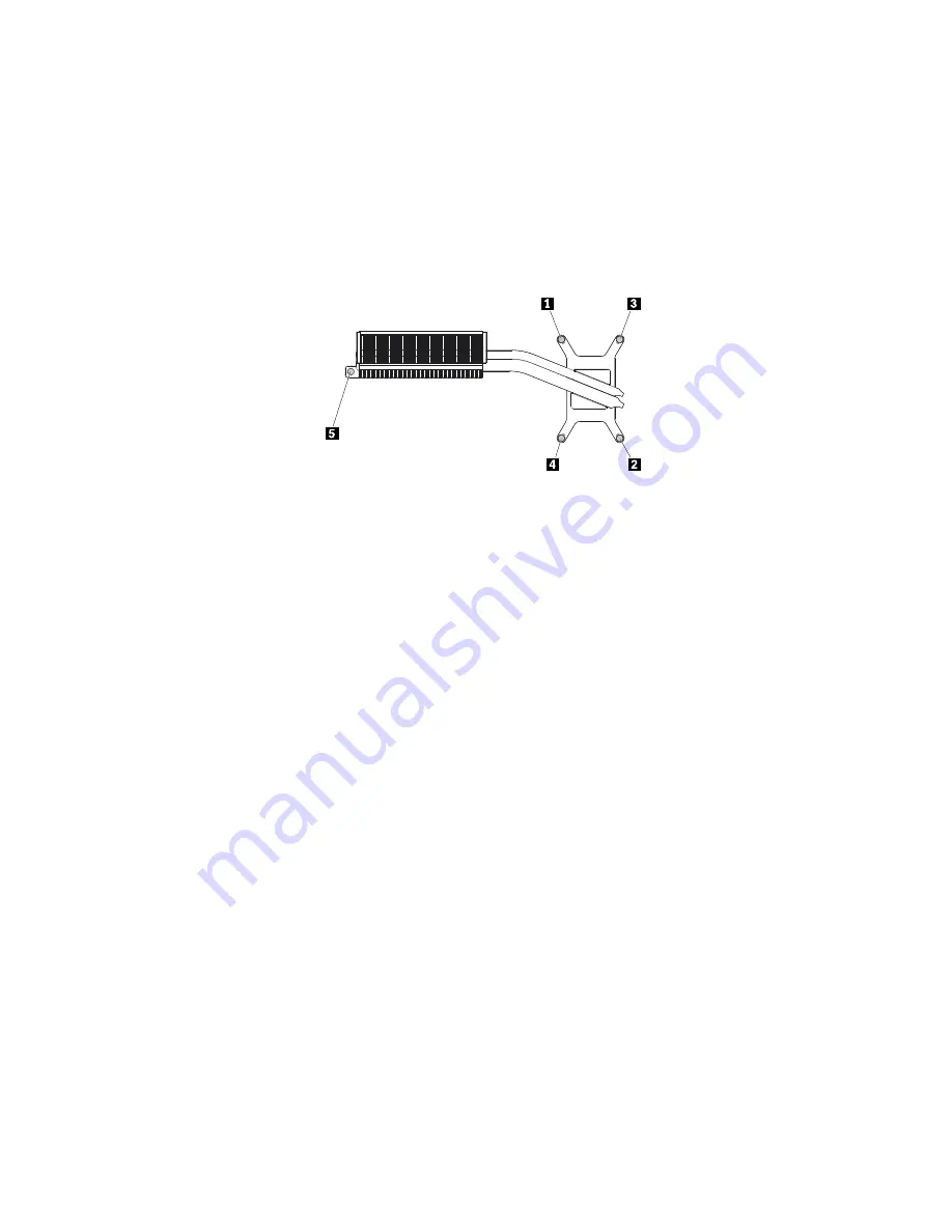
6. Follow the sequence shown below to loosen screw 1 through screw 5, and then remove the heat
sink from the chassis.
Notes:
a. Carefully remove the five screws from the system board to avoid any possible damage to the system
board. The five screws cannot be removed from the heat sink.
b. You might have to gently twist the heat sink to free it from the microprocessor.
c. Do not touch the thermal grease while handling the heat sink.
Figure 49. Removing the heat sink
7. Align the four screws in the new heat sink with the corresponding screw holes in the system board.
Then, follow the sequence shown above to tighten the five screws to secure the heat sink.
8. Reinstall the system board shield. See “Replacing the system board shield” on page 98.
9. Reinstall the computer cover. See “Replacing the computer cover” on page 95.
What to do next:
• To work with another piece of hardware, go to the appropriate section.
• To complete the installation or replacement, go to “Completing the parts replacement” on page 116.
Replacing the system board
Attention:
Do not open your computer or attempt any repair before reading and understanding the Chapter
1 “Read this first: Important safety information” on page 1.
Note:
Each computer has a unique Vital Product Data (VPD) code stored in the nonvolatile memory on
the system board. After you replace the system board, the VPD must be updated. To update the VPD,
see “Updating the BIOS” on page 68.
To replace the system board, do the following:
1. Remove any media from the drives and turn off all connected devices and the computer. Then,
disconnect all power cords from electrical outlets and disconnect all cables that are connected to the
computer.
2. Remove the back cover. See “Removing the back cover” on page 90.
3. Remove the computer cover. See “Replacing the computer cover” on page 95.
4. Remove the system board shield. See “Replacing the system board shield” on page 98.
5. Remove the Wi-Fi card. See “Replacing the Wi-Fi card” on page 107.
6. Remove the memory modules. See “Replacing a memory module” on page 92.
7. Remove the heat sink. See “Replacing the heat sink” on page 111.
8. Remove the card reader. See “Replacing the card reader” on page 110.
112
ThinkCentre M900z Hardware Maintenance Manual
Summary of Contents for ThinkCentre M900z 10F2
Page 1: ...ThinkCentre M900z Hardware Maintenance Manual Machine Types 10F2 10F3 10F4 and 10F5 ...
Page 6: ...iv ThinkCentre M900z Hardware Maintenance Manual ...
Page 8: ...vi ThinkCentre M900z Hardware Maintenance Manual ...
Page 16: ...8 ThinkCentre M900z Hardware Maintenance Manual ...
Page 20: ...12 ThinkCentre M900z Hardware Maintenance Manual ...
Page 21: ...1 2 Chapter 1 Read this first Important safety information 13 ...
Page 22: ...1 2 14 ThinkCentre M900z Hardware Maintenance Manual ...
Page 27: ...1 2 Chapter 1 Read this first Important safety information 19 ...
Page 28: ...1 2 20 ThinkCentre M900z Hardware Maintenance Manual ...
Page 31: ...Chapter 1 Read this first Important safety information 23 ...
Page 40: ...31 32 ThinkCentre M900z Hardware Maintenance Manual ...
Page 50: ...42 ThinkCentre M900z Hardware Maintenance Manual ...
Page 66: ...58 ThinkCentre M900z Hardware Maintenance Manual ...
Page 128: ...120 ThinkCentre M900z Hardware Maintenance Manual ...
Page 136: ...128 ThinkCentre M900z Hardware Maintenance Manual ...
Page 138: ...China RoHS 130 ThinkCentre M900z Hardware Maintenance Manual ...
Page 139: ...Appendix D China Energy Label Copyright Lenovo 2015 131 ...
Page 140: ...132 ThinkCentre M900z Hardware Maintenance Manual ...
Page 142: ...134 ThinkCentre M900z Hardware Maintenance Manual ...
Page 145: ......
Page 146: ......