


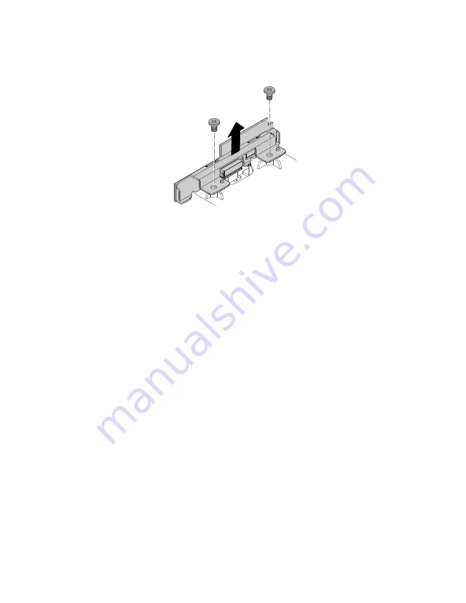
8. Remove the two screws that secure the control button board, and then remove the control button
board from the computer cover.
Figure 33. Removing the control button board
9. Align the two holes in the control button board with the corresponding screw holes in the new computer
cover. Then, install the two screws to secure the control button board.
10. Position the new computer cover on the chassis, and then press the computer cover downward until the
three tabs snap into position. Tighten the two screws to secure the computer cover.
11. Install the side I/O bracket by inserting the two tabs on the side I/O bracket into the corresponding
holes in the computer cover.
12. Connect the control button board cable to the control button board.
13. Slide the optical drive into the optical drive bay until it snaps into position, and then tighten the screw
to secure the optical drive.
What to do next:
• To work with another piece of hardware, go to the appropriate section.
• To complete the installation or replacement, go to “Completing the parts replacement” on page 116.
Replacing the system board shield
Attention:
Do not open your computer or attempt any repair before reading and understanding the Chapter
1 “Read this first: Important safety information” on page 1.
To replace the system board shield, do the following:
1. Remove any media from the drives and turn off all connected devices and the computer. Then,
disconnect all power cords from electrical outlets and disconnect all cables that are connected to the
computer.
2. Remove the back cover. See “Removing the back cover” on page 90.
3. Remove the computer cover. See “Replacing the computer cover” on page 95.
4. Remove the memory module shield. See “Replacing the memory module shield” on page 91.
5. Locate the system board shield. See “Major FRUs and CRUs” on page 31.
98
ThinkCentre M900z Hardware Maintenance Manual
Summary of Contents for ThinkCentre M900z 10F2
Page 1: ...ThinkCentre M900z Hardware Maintenance Manual Machine Types 10F2 10F3 10F4 and 10F5 ...
Page 6: ...iv ThinkCentre M900z Hardware Maintenance Manual ...
Page 8: ...vi ThinkCentre M900z Hardware Maintenance Manual ...
Page 16: ...8 ThinkCentre M900z Hardware Maintenance Manual ...
Page 20: ...12 ThinkCentre M900z Hardware Maintenance Manual ...
Page 21: ...1 2 Chapter 1 Read this first Important safety information 13 ...
Page 22: ...1 2 14 ThinkCentre M900z Hardware Maintenance Manual ...
Page 27: ...1 2 Chapter 1 Read this first Important safety information 19 ...
Page 28: ...1 2 20 ThinkCentre M900z Hardware Maintenance Manual ...
Page 31: ...Chapter 1 Read this first Important safety information 23 ...
Page 40: ...31 32 ThinkCentre M900z Hardware Maintenance Manual ...
Page 50: ...42 ThinkCentre M900z Hardware Maintenance Manual ...
Page 66: ...58 ThinkCentre M900z Hardware Maintenance Manual ...
Page 128: ...120 ThinkCentre M900z Hardware Maintenance Manual ...
Page 136: ...128 ThinkCentre M900z Hardware Maintenance Manual ...
Page 138: ...China RoHS 130 ThinkCentre M900z Hardware Maintenance Manual ...
Page 139: ...Appendix D China Energy Label Copyright Lenovo 2015 131 ...
Page 140: ...132 ThinkCentre M900z Hardware Maintenance Manual ...
Page 142: ...134 ThinkCentre M900z Hardware Maintenance Manual ...
Page 145: ......
Page 146: ......