Contents
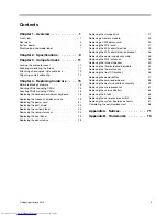
Chapter 1. Overview . . . . . . . . . . . 1
Front view . . . . . . . . . . . . . . . . . . 1
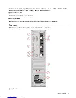
Rear view . . . . . . . . . . . . . . . . . . 3
System board
. . . . . . . . . . . . . . . . 5
Machine type and model label . . . . . . . . . . 7
Chapter 2. Specifications . . . . . . . . 9
Chapter 3. Computer locks . . . . . . 11
Locking the computer cover . . . . . . . . . . 11
Enabling or disabling the E-lock . . . . . . . . 11
Attaching a Kensington-style cable lock . . . . . 12
Attaching a smart cable clip . . . . . . . . . . 12
Chapter 4. Replacing hardware . . . . 15
Before replacing hardware
. . . . . . . . . . 15
Knowing FRUs (including CRUs) . . . . . . . . 15
Locating FRUs (including CRUs) . . . . . . . . 16
Replacing the keyboard or wireless keyboard . . . 18
Replacing the mouse or wireless mouse . . . . . 19
Replacing the power cord . . . . . . . . . . . 21
Replacing the dust shield . . . . . . . . . . . 22
Replacing the vertical stand . . . . . . . . . . 23
Removing the computer cover . . . . . . . . . 24
Replacing the front bezel . . . . . . . . . . . 25
Replacing the optical drive . . . . . . . . . . 25
Replacing the storage drive . . . . . . . . . . 27
Replacing a memory module. . . . . . . . . . 33
Replacing a PCI Express card . . . . . . . . . 35
Replacing the Wi-Fi card . . . . . . . . . . . 37
Replacing the M.2 solid-state drive . . . . . . . 39
Replacing the M.2 solid-state drive bracket . . . . 46
Replacing the power supply assembly . . . . . . 46
Replacing the Wi-Fi antennas . . . . . . . . . 48
Replacing the internal speaker . . . . . . . . . 50
Replacing the illuminated red dot cable
. . . . . 52
Replacing the thermal sensor . . . . . . . . . 54
Replacing the front I/O bracket . . . . . . . . . 56
Replacing the power button . . . . . . . . . . 57
Replacing the card reader board . . . . . . . . 58
Replacing the heat sink and fan assembly
. . . . 59
Replacing the microprocessor . . . . . . . . . 61
Replacing the coin-cell battery . . . . . . . . . 63
Replacing the E-lock . . . . . . . . . . . . . 65
Replacing the cover presence switch . . . . . . 66
Replacing the system board and chassis . . . . . 67
Completing the parts replacement . . . . . . . 68
Appendix A. Notices . . . . . . . . . . 71
Appendix B. Trademarks . . . . . . . 73
© Copyright Lenovo 2018
i
Summary of Contents for ThinkCentre M720s
Page 4: ...ii ThinkCentre M720s User Guide and Hardware Maintenance Manual ...
Page 12: ...8 ThinkCentre M720s User Guide and Hardware Maintenance Manual ...
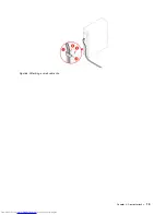
Page 17: ...Figure 8 Attaching a smart cable clip Chapter 3 Computer locks 13 ...
Page 18: ...14 ThinkCentre M720s User Guide and Hardware Maintenance Manual ...
Page 74: ...70 ThinkCentre M720s User Guide and Hardware Maintenance Manual ...
Page 76: ...72 ThinkCentre M720s User Guide and Hardware Maintenance Manual ...
Page 78: ...74 ThinkCentre M720s User Guide and Hardware Maintenance Manual ...
Page 79: ......
Page 80: ......

