


Step 2.
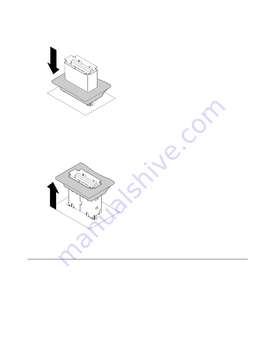
Unlock the retention latch by pushing it down toward the system board.
Figure 80. Unlock retention latch
Step 3.
Align the flash device with the USB connector on the system board and push it into the USB
connector until it is firmly seated.
Step 4.
Return the retention latch to the locked position by pulling it away from the system board.
Figure 81. Return retention latch
If you have other devices to install or remove, do so now.
Completing the installation
Use this information to complete the installation.
To complete the installation, complete the following steps.
Step 1.
If you removed the fan cage assembly, reinstall it (see “Replacing the fan cage assembly” on
page 97).
Step 2.
If you removed the air baffle, reinstall it (see “Replacing the air baffle” on page 99).
Step 3.
If you removed the server cover, replace it (see “Replacing the left-side cover” on page 99).
Step 4.
Reconnect the cables and power cords (see “Connecting the cables” on page 100).
Step 5.
Update the server configuration (see “Updating the server configuration” on page 102).
96
System x3500 M4 Installation and Service Guide
Summary of Contents for System x3500 M4
Page 1: ...System x3500 M4 Installation and Service Guide Machine Type 7383 ...
Page 6: ...iv System x3500 M4 Installation and Service Guide ...
Page 14: ...xii System x3500 M4 Installation and Service Guide ...
Page 140: ...126 System x3500 M4 Installation and Service Guide ...
Page 180: ...166 System x3500 M4 Installation and Service Guide ...
Page 194: ...180 System x3500 M4 Installation and Service Guide ...
Page 978: ...964 System x3500 M4 Installation and Service Guide ...
Page 1002: ...988 System x3500 M4 Installation and Service Guide ...
Page 1160: ...1146 System x3500 M4 Installation and Service Guide ...
Page 1164: ...1150 System x3500 M4 Installation and Service Guide ...
Page 1172: ...Taiwan BSMI RoHS declaration 1158 System x3500 M4 Installation and Service Guide ...
Page 1181: ......
Page 1182: ......


