background image

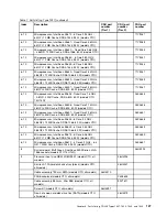
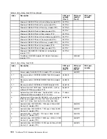
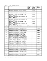
Table 8. Parts listing, Type 1029 (continued)

Index

Description

CRU part
number
(Tier 1)

CRU part
number
(Tier 2)

FRU part
number

Windows 2008 R2 STD 64 bit United Sates (models CTO)

90Y1183

Windows 2008 R2 STD 64 bit France (models CTO)

90Y1184

Windows 2008 R2 STD 64 bit Germany (models CTO)

90Y1185

Windows 2008 R2 STD 64 bit Spain (models CTO)

90Y1187

Windows 2008 R2 STD 64 bit Italy (models CTO)

90Y1188

Windows 2008 R2 ENT 64 bit United Sates (models CTO)

90Y1191

Windows 2008 R2 ENT 64 bit France (models CTO)

90Y1193

Windows 2008 R2 ENT 64 bit Germany (models CTO)

90Y1194

Windows 2008 R2 ENT 64 bit Italy (models CTO)

90Y1195

Windows 2008 R2 ENT 64 bit Spain (models CTO)

90Y1197

Windows 2008 SBS SP2 PREM 64 bit United Sates
(models CTO)

90Y1182

ThinkServer RAID 500 Adapter B-2 (Raid 5 Controller)
(models CTO)

03X3635

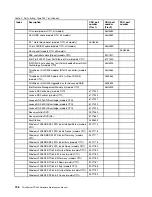
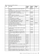
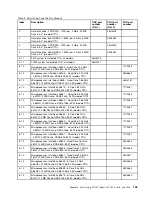
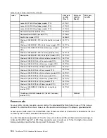
Table 9. Parts listing, Type 1039

Index

Description

CRU part
number
(Tier 1)

CRU part
number
(Tier 2)

FRU part
number

1

Power supply, Delta 625 W PSU (models CTO, all models)

46U3201

2, 7

Memory module, 2 GB DDR3 RDIMM 1333 MHz (models
CTO)

46U3442

2, 7

Memory module, 4 GB DDR3 RDIMM 1333 MHz (models
CTO)

46U3443

2, 7

Memory module, 2 GB DDR3 LV RDIMM (models CTO)

46U3193

3

Optical drive, DVD-ROM drive - 16x/48x SATA - with no
software (DOS/Linux) (models CTO)

46U3191

3

Optical drive, DVD-ROM drive - 16x/48x SATA - with no
software (DOS/Linux) (models CTO, 11G, 12U)

71Y5543

3

Optical drive, DVD burner/CD-RW SATA - with no software
(DOS/Linux) (models CTO 13U 13G 14G 15U 15G 16U
16G 17U 17G 18U 18G 19U 19G 1AU 1AG 1BU 1BG)

46U3206

4

Hard disk drive, 250 GB SATA - 7200 rpm, 3 Gb/s, 8 MB
Cache, 3.5" (models CTO)

46U3100

4

Hard disk drive, 500 GB SATA - 7200 rpm, 3 Gb/s, 16 MB
Cache, 3.5" (models CTO)

46U3101

4

Hard disk drive, 1 TB SATA - 7200 rpm, 3 Gb/s, 32 MB
Cache, 3.5" (models CTO)

46U3103

4

Hard disk drive, 300 GB SAS - 15000 rpm, 3 Gb/s, 32 MB
Cache, 3.5" (models CTO)

46U3572

4

Hard disk drive, 450 GB SAS - 15000 rpm, 36 Gb/s, 32 MB
Cache, 3.5" (models CTO)

46U3573

132

ThinkServer TD230 Hardware Maintenance Manual

Summary of Contents for and 1040

Page 1: ...ThinkServer TD230 Hardware Maintenance Manual Machine Types 1027 1029 1039 and 1040 ...

Page 2: ......

Page 3: ...ThinkServer TD230 Hardware Maintenance Manual Machine Types 1027 1029 1039 and 1040 ...

Page 4: ...nd Support Information document on the ThinkServer Documentation DVD Eighth Edition October 2011 Copyright Lenovo 2010 2011 LIMITED AND RESTRICTED RIGHTS NOTICE If data or software is delivered pursuant a General Services Administration GSA contract use reproduction or disclosure is subject to restrictions set forth in Contract No GS 35F 05925 ...

Page 5: ...s 39 Basic guidelines 39 System reliability guidelines 40 Handling static sensitive devices 40 Working inside the server with the power on 41 Guidelines for trained service technicians 41 Inspecting for unsafe conditions 41 Guidelines for servicing electrical equipment 42 Removing the server cover 43 Removing and reinstalling the front bezel 45 Locking or unlocking the hard disk drive side door 46...

Page 6: ...oller 157 Updating the firmware 158 Using the EasyUpdate Firmware Updater program 158 Installing the ThinkServer EasyManage program 158 Appendix A RAID battery card assembly 161 Specifications 161 Battery life and data retention time 161 Appendix B Getting help and technical assistance 163 Before you call 163 Using the documentation 163 Getting help and information from the World Wide Web 163 Call...

Page 7: ...rvice and assistance see the Warranty and Support Information document Safety information Note Before using the product be sure to read and understand the multilingual safety instructions on the documentation DVD that comes with the product Antes de usar o produto leia e entenda as instruções de segurança multilíngues no DVD de documentação que o acompanha Преди да използвате този продукт задължит...

Page 8: ...ente as instruções de segurança multilingues que constam no DVD de documentação fornecido com o produto Înainte de a utiliza produsul asiguraţi vă că aţi citit şi înţeles instrucţiunile de siguranţă în mai multe limbi de pe DVD ul cu documentaţie care însoţeşte produsul Før du bruker produktet må du lese og forstå den flerspråklige sikkerhetsinformasjonen på DVDen med dokumentasjon som følger med ...

Page 9: ...tatement 1 DANGER Electrical current from power telephone and communication cables is hazardous To avoid a shock hazard Do not connect or disconnect any cables or perform installation maintenance or reconfiguration of this product during an electrical storm Connect all power cords to a properly wired and grounded electrical outlet Connect to properly wired outlets any equipment that will be attach...

Page 10: ...such as CD ROMs DVD drives fiber optic devices or transmitters are installed note the following Do not remove the covers Removing the covers of the laser product could result in exposure to hazardous laser radiation There are no serviceable parts inside the device Use of controls or adjustments or performance of procedures other than those specified herein might result in hazardous radiation expos...

Page 11: ...To remove all electrical current from the device ensure that all power cords are disconnected from the power source Statement 6 CAUTION If you install a strain relief bracket option over the end of the power cord that is connected to the device you must connect the other end of the power cord to an easily accessible power source Statement 7 CAUTION If the device has doors be sure to remove or secu...

Page 12: ... the hot swap fan cables before removing the fan from the device Statement 10 CAUTION The following label indicates sharp edges corners or joints nearby Statement 11 CAUTION The following label indicates a hot surface nearby Statement 12 DANGER Overloading a branch circuit is potentially a fire hazard and a shock hazard under certain conditions To avoid these hazards ensure that your system electr...

Page 13: ...uipment must be installed by trained service personnel in a restricted access location as defined by the NEC and the latest edition of IEC 60950 The Standard for Safety of Information Technology Equipment Connect the equipment to a reliably grounded safety extra low voltage SELV source An SELV source is a secondary circuit that is designed so that normal and single fault conditions do not cause th...

Page 14: ...d on Lenovo products placed on the market and sold in the European Union after June 2006 Products on the market before June 2006 are not required to have RoHS compliant parts If the parts are not compliant originally replacement parts can also be noncompliant but in all cases if the parts are compliant the replacement parts must also be compliant Note RoHS and non RoHS FRU part numbers with the sa...

Page 15: ...ions for those FRUs can be used Products marketed before June 2006 Products marketed after June 2006 Current or original part Replacement FRU Current or original part Replacement FRU Non RoHS Can be Non RoHS Non RoHS Can be RoHS Non RoHS Can sub to RoHS RoHS Must be RoHS Must be RoHS Must be RoHS Note A direct substitution is a part with a different FRU part number that is automatically shipped by...

Page 16: ...10 ThinkServer TD230 Hardware Maintenance Manual ...

Page 17: ... four DIMMs if one microprocessor installed Two four six or eight DIMMs if two microprocessors installed Integrated video controller The server comes with an onboard high performance graphics controller that supports high resolutions and includes many performance enhancing features for the operating system environment 64 MB memory 32 MB for video memory cache Optical drive SATA DVD RW Hard disk dr...

Page 18: ...127 V ac Input frequency range 50 to 60 Hz High range Minimum 200 V ac Maximum 240 V ac Input frequency range 50 to 60 Hz Software programs Lenovo provides software to help get your server up and running EasyStartup The ThinkServer EasyStartup program simplifies the process of configuring RAID and installing supported Microsoft Windows and Linux operating systems and device drivers on your server ...

Page 19: ... Detect SPD Error codes and messages to help you identify problems Generating error logs for the power on self test POST failures Hot swap SAS hard disk drives Integrated Ethernet controllers Intelligent Platform Management Interface IPMI 2 0 Power on self test POST Standby voltage for system management features and monitoring System error light emitting diode LED on the front panel Vital product ...

Page 20: ...14 ThinkServer TD230 Hardware Maintenance Manual ...

Page 21: ... the problem is solved See the parts listing in the Hardware Maintenance Manual to determine which components are customer replaceable units CRUs and which components are field replaceable units FRUs If an action step is preceded by Trained service technician only that step must be performed only by a trained service technician Symptom Action The DVD drive is not recognized 1 Make sure that The SA...

Page 22: ...eable units FRUs If an action step is preceded by Trained service technician only that step must be performed only by a trained service technician Symptom Action Not all drives are recognized by the hard disk drive diagnostic tests Remove the drive that is indicated by the diagnostic tests then run the hard disk drive diagnostic tests again If the remaining drives are recognized replace the drive ...

Page 23: ... compatible with the server Refer to the Web site at http www lenovo com thinkserver 3 If you are using a USB keyboard and it is connected to a USB hub disconnect the keyboard from the hub and connect it directly to the server 4 Replace the following components one at a time in the order shown restarting the server each time a Keyboard b Trained service technician only System board The mouse or po...

Page 24: ...figuration 4 Add one pair of DIMMs at a time making sure that the DIMMs in each pair are matching 5 Reseat the DIMMs 6 Replace the DIMMs in step 5 on page 18 one at a time in the order shown restarting the server each time Multiple rows of DIMMs in a branch are identified as failing 1 Reseat the DIMMs then restart the server 2 Replace the lowest numbered DIMMs with identical known good DIMMs then ...

Page 25: ...ng and adjusting the monitor Follow the suggested actions in the order in which they are listed in the Action column until the problem is solved See the parts listing in the Hardware Maintenance Manual to determine which components are customer replaceable units CRUs and which components are field replaceable units FRUs If an action step is preceded by Trained service technician only that step mus...

Page 26: ...seat the monitor 3 Replace the following components one at a time in the order shown restarting the server each time a Monitor b Trained service technician only System board Optional device problems Follow the suggested actions in the order in which they are listed in the Action column until the problem is solved See the parts listing in the Hardware Maintenance Manual to determine which component...

Page 27: ...an Symptom Action The power control button does not work the server does not start Note The power control button will not function until 3 minutes after the server has been connected to ac power 1 Make sure that the power control button is working correctly a Disconnect the server power cords b Reconnect the power cords c Trained service technician only Reseat the operator information panel cables...

Page 28: ...d in the Action column until the problem is solved See the parts listing in the Hardware Maintenance Manual to determine which components are customer replaceable units CRUs and which components are field replaceable units FRUs If an action step is preceded by Trained service technician only that step must be performed only by a trained service technician Symptom Action The number of serial ports ...

Page 29: ...der in which they are listed in the Action column until the problem is solved See the parts listing in the Hardware Maintenance Manual to determine which components are customer replaceable units CRUs and which components are field replaceable units FRUs If an action step is preceded by Trained service technician only that step must be performed only by a trained service technician Symptom Action ...

Page 30: ...controller manually to match the speed and duplex mode of the hub Check the Ethernet controller LEDs on the rear panel of the server These LEDs indicate whether there is a problem with the connector cable or hub The Ethernet link status LED is lit when the Ethernet controller receives a link pulse from the hub If the LED is off there might be a defective connector or cable or a problem with the hu...

Page 31: ...er if the problem recurs when you replace the adapter with a different one suspect the system board or extender card If you suspect a networking problem and the server passes all the system tests suspect a network cabling problem that is external to the server Event logs Error codes and messages are displayed in the following types of event logs POST event log This log contains the three most rece...

Page 32: ...inues booting Note For 0048 Password check failed the system will halt and then after the next reset reboot displays the error code on the Error Manager screen Fatal The system halts during the POST at a blank screen with the text Unrecoverable fatal error found System will not boot until the error is resolved and Press F2 to enter setup The POST Error Pause option setting in the BIOS setup does n...

Page 33: ...w Figure 1 Front view of the server on page 27 shows the LEDs and parts on the front of the server Figure 1 Front view of the server 1 Power LED 4 System status LED 2 Hard disk drive status LED 5 Front door lock 3 Ethernet status LED 6 Logo plate You can open the front door with the key to locate controls LEDs connectors and other parts on the front panel Copyright Lenovo 2010 2011 27 ...

Page 34: ...nt door Figure 3 Front view of the server with the front door open on page 29 shows the controls LEDs connectors and other parts on the front panel after you open the front door 28 ThinkServer TD230 Hardware Maintenance Manual ...

Page 35: ...e following table describes the various meanings of the status LEDs on the front panel of your server Table 2 Meanings of the status LEDs on the front panel LED State Color Description On Green The server is on Blinking Green The server is in sleep mode Power LED Off Off The server is off Off Off The hard disk drive is not active Hard disk drive status LED Blinking Green The hard disk drive is act...

Page 36: ...n This applies to one of the following situations The microprocessor is missing The microprocessor temperature is too high The unrecoverable temperature threshold is asserted The unrecoverable voltage threshold is asserted The system has a power fault or a power control failure System status LED Blinking Amber This is a non fatal alarm which means that the system is likely to fail This applies to ...

Page 37: ...et connector 1 4 USB connectors 4 8 Front door key cut the plastic clip to get the key Hot swap hard disk drive status LEDs For server models with hot swap hard disk drives each hot swap hard disk drive also has two status LEDs on the front Figure 5 Hot swap hard disk drive status LEDs Chapter 4 Locating parts controls LEDs and connectors 31 ...

Page 38: ...ion and activity of the connection Table 4 Ethernet LEDs LED State Color Description On Green 10 100 1000 Mb linked Blinking Green 10 100 1000 Mb activity RJ 45 Linkage and Activity left Off Off No LAN connection On Amber 1000 Mb linked and active On Green 100 Mb linked and active RJ 45 Linkage and Activity right Off Off 10 Mb mode or no LAN connection Locating server components Figure 6 Server co...

Page 39: ...1 14 Rear fan system fan 3 7 Microprocessor 2 socket the second microprocessor is optional 15 System board battery 8 Memory slots for microprocessor 2 some slots might with installed memory modules 16 System board Note denotes that this illustration only shows the server models with four hot swap hard disk drives There are also server models that support up to five non hot swap hard disk drives Lo...

Page 40: ...or 1 heat sink and fan assembly connector 25 SATA connector 5 9 Microprocessor power connector 26 PCI Express x4 slot 10 Microprocessor 1 27 PCI card slot 11 Microprocessor 2 socket the second microprocessor is optional 28 Remote management module 3 RMM3 connector 12 Microprocessor 2 heat sink and fan assembly connector 29 PCI Express x8 slot 13 System fan 1 connector 30 PCI Express x8 slot 14 Mem...

Page 41: ...drive LED 7 Microprocessor 2 heat sink fan fault LED 2 System fan 3 fault LED 8 System fan 1 fault LED 3 5 VSB LED 9 DIMM fault LEDs 4 4 DIMM fault LEDs 4 10 Post code diagnostic LEDs 5 System fan 2 fault LED 11 Status LED 6 Microprocessor 1 heat sink fan fault LED 12 System ID LED Jumper block settings There are several jumper blocks on the system board that can be used to configure recover or en...

Page 42: ...very Pins 2 3 The main system BIOS will not boot with these pins jumpered The system will boot from a bootable recovery media with a recovery BIOS image Pins 1 2 These pins should have a jumper in place for normal system operation default 4 J2D2 CMOS clear Pins 2 3 If these pins are jumpered the CMOS settings will be cleared on the next reset These pins should not be jumpered for normal operation ...

Page 43: ... hot swap hard disk drive backplanes on page 37 shows the connector locations on the hot swap hard disk drive backplanes Figure 10 Connector locations on the hot swap hard disk drive backplanes 1 SATA SAS signal connector 2 7 Hot swap hard disk drive 1 connector 2 SATA SAS signal connector 3 8 Hot swap hard disk drive 0 connector 3 Power connector 9 First hot swap hard disk drive backplane 4 Hot s...

Page 44: ...38 ThinkServer TD230 Hardware Maintenance Manual ...

Page 45: ...fore you install optional hardware devices make sure that the server is working correctly If an operating system is installed turn on the server and make sure that the operating system starts If no operating system is installed make sure that a 19990305 error code is displayed indicating that an operating system was not found but the server is working correctly If the server is not working correct...

Page 46: ...he server is running Operating the server without the air duct or air baffles might cause the microprocessor to overheat The second microprocessor socket always contains either a microprocessor socket cover or a microprocessor and heat sink Handling static sensitive devices Attention Do not open the static protective package containing the new part until the defective part has been removed from th...

Page 47: ...se the information in this section to help you identify potential unsafe conditions in a Lenovo product that you are working on Each Lenovo product as it was designed and manufactured has required safety items to protect users and service technicians from injury The information in this section addresses only those items Use good judgment to identify potential unsafe conditions that might be caused...

Page 48: ...ncy power off EPO switch disconnecting switch or electrical outlet so that you can turn off the power quickly in the event of an electrical accident Disconnect all power before you perform a mechanical inspection work near power supplies or remove or install main units Before you work on the equipment disconnect the power cord If you cannot disconnect the power cord have the customer power off the...

Page 49: ...instructions on how to remove the server cover Attention For proper cooling and airflow install the server cover before turning on the server Operating the server for more than 30 minutes with the server cover removed might damage server components To remove the server cover do the following 1 Remove all media from the drives Then turn off all attached devices and the server 2 Disconnect all power...

Page 50: ... two thumbscrews are securely installed and you need to use a tool for example a screw driver to loosen the thumbscrews b The two thumbscrews are integrated parts of the server cover and they cannot be removed from the server cover Figure 11 Sliding the server cover to the rear 44 ThinkServer TD230 Hardware Maintenance Manual ...

Page 51: ...ver Documentation DVD that came with your product and Guidelines on page 39 To obtain a copy of the publications go to http www lenovo com support This section provides instructions on how to remove and reinstall the front bezel To remove and reinstall the front bezel do the following 1 Remove all media from the drives and turn off all attached devices and the server Then disconnect all power cord...

Page 52: ... left side 5 Go to Completing the parts replacement on page 122 Locking or unlocking the hard disk drive side door Attention Do not open your server or attempt any repair before reading and understanding the Safety Information and the Warranty and Support Information on the ThinkServer Documentation DVD that came with your product and Guidelines on page 39 To obtain a copy of the publications go t...

Page 53: ...rd disk drive side door to ensure that all the hard disk drives cannot be accessed unless you remove the server cover If you do so you must turn off the server disconnect all power cords and remove the server cover when you want to replace any hard disk drives including the hot swap hard disk drives To lock or unlock the hard disk drive side door do the following 1 Press the blue button 1 to open ...

Page 54: ... door to the closed position Then close the side door until it snaps into position The side door is locked and cannot be opened when you press the blue button Figure 15 Locking the side door 48 ThinkServer TD230 Hardware Maintenance Manual ...

Page 55: ...e installation procedure for the optional hardware device that you want to replace Installing or removing a memory module This section provides instructions on how to install or remove a memory module For a list of the supported memory modules for your server go to http www lenovo com thinkserver On the ThinkServer systems page click Products Options ThinkServer Memory Memory module installation r...

Page 56: ...e with your product and Guidelines on page 39 To obtain a copy of the publications go to http www lenovo com support This section provides instructions on how to install a memory module To install a memory module do the following 1 Remove all media from the drives and turn off all attached devices and the server Then disconnect all power cords from electrical outlets and disconnect all cables that...

Page 57: ...nto position Note If there is a gap between the memory module and the retaining clips the memory module has not been correctly installed Open the retaining clips remove the memory module and then reinstall it into the slot Figure 18 Installing the memory module 7 To complete the installation go to Completing the parts replacement on page 122 Removing a memory module Attention Do not open your serv...

Page 58: ...see Locating server components on page 32 for the locations of the drive bays in the server When installing an internal drive be sure to consider the following information Make sure that you have all the cables and other equipment specified in the documentation that came with the drive Note the type and size of the drive and select the appropriate drive bay to install the drive Check the instructi...

Page 59: ... the following 1 Remove all media from the drives and turn off all attached devices and the server Then disconnect all power cords from electrical outlets and disconnect all cables that are connected to the server 2 Remove the server cover See Removing the server cover on page 43 3 Remove the front bezel See Removing and reinstalling the front bezel on page 45 4 Disconnect the signal cable and the...

Page 60: ...drive do the following 1 If you are replacing the optical drive make sure that You have all the cables and other equipment that is specified in the documentation that comes with the new optical drive You have checked the instructions that come with the new optical drive to determine whether you must set any switches or jumpers in the optical drive You have removed the optical drive retainers from ...

Page 61: ...s that are connected to the server 3 Remove the server cover See Removing the server cover on page 43 4 Remove the front bezel See Removing and reinstalling the front bezel on page 45 5 Touch the static protective package that contains the new optical drive to any unpainted metal surface on the server Then remove the new optical drive from the package and place it on a static protective surface 6 ...

Page 62: ... to an available SATA connector SATA connector 5 recommended on the system board See Locating parts on the system board on page 33 Then locate an available five wire power connector 1 and connect it to the rear of the new optical drive Figure 24 Connecting the optical drive cables 9 To complete the installation go to Completing the parts replacement on page 122 56 ThinkServer TD230 Hardware Mainte...

Page 63: ...talled Attention To maintain proper system cooling do not operate the server for more than 10 minutes without either a drive or a filler panel installed in each drive bay To remove a hot swap hard disk drive do the following Note You do not have to turn off the server when removing a hot swap hard disk drive However if you have locked the side door you must turn off the server disconnect all power...

Page 64: ...want to remove Then press the blue release button 1 and rotate the handle of the hard disk drive bracket to the open position Figure 26 Opening the handle of the hot swap hard disk drive bracket 58 ThinkServer TD230 Hardware Maintenance Manual ...

Page 65: ...sp the handle 1 and pull the hard disk drive bracket with the hard disk drive out of the drive bay Figure 27 Removing the hot swap hard disk drive bracket with the hard disk drive Chapter 5 Replacing FRUs 59 ...

Page 66: ...tp www lenovo com support This section provides instructions on how to install a hot swap hard disk drive This section applies only to server models that support hot swap hard disk drives Attention To maintain proper system cooling do not operate the server for more than 10 minutes without either a drive or a filler panel installed in each drive bay To install a hot swap hard disk drive do the fol...

Page 67: ...1 Press the blue button 1 to open the side door Figure 29 Opening the side door Chapter 5 Replacing FRUs 61 ...

Page 68: ...nt to install the drive Then press the blue release button 1 and rotate the handle of the hard disk drive bracket to the open position Figure 30 Opening the handle of the hot swap hard disk drive bracket 62 ThinkServer TD230 Hardware Maintenance Manual ...

Page 69: ...e or PCI card save the EMC shield or drive bay filler from the drive bay or save the PCI card slot cover in the event that you later remove the device An unoccupied drive bay or PCI card slot without cover shield filler or any other protection might impact the EMI integrity and cooling of the server which might result in overheating or component damage 5 Touch the static protective package that co...

Page 70: ...out touching the circuit board on the bottom of the hard disk drive Figure 32 Installing the hard disk drive into the bracket 7 Keep the handle of the hot swap hard disk drive bracket fully open and then slide the bracket with the hard disk drive into the drive bay until it cannot be pushed in anymore Figure 33 Sliding the hot swap hard disk drive bracket with the hard disk drive into the bay 64 T...

Page 71: ... be replaced if the green hard disk drive status LED is blinking this indicates that the hard disk drive is operating correctly Note If the server is configured for RAID operation using a RAID controller you might have to reconfigure the disk arrays after you replace hard disk drives 10 To complete the installation go to Completing the parts replacement on page 122 Removing a non hot swap hard dis...

Page 72: ...ll media from the drives and turn off all attached devices and the server Then disconnect all power cords from electrical outlets and disconnect all cables that are connected to the server 2 Press the blue button 1 to open the side door Note If you have locked the side door you must turn off the server disconnect all power cords and remove the server cover when you want to remove install or replac...

Page 73: ...l the handle of the hard disk drive bracket to slide the bracket with the hard disk drive out of the drive bay Figure 36 Disconnecting cables and sliding the non hot swap hard disk drive out 4 Depending on the non hot swap hard disk drive is secured in the bracket by screws or plastic retainers do one of the following Chapter 5 Replacing FRUs 67 ...

Page 74: ...al procedure go to Completing the parts replacement on page 122 Installing a non hot swap hard disk drive Attention Do not open your server or attempt any repair before reading and understanding the Safety Information and the Warranty and Support Information on the ThinkServer Documentation DVD that came with your product and Guidelines on page 39 To obtain a copy of the publications go to http ww...

Page 75: ...2 Press the blue button 1 to open the side door Note If you have locked the side door you must turn off the server disconnect all power cords and remove the server cover when you want to remove install or replace any hard disk drives See Locking or unlocking the hard disk drive side door on page 46 and Removing the server cover on page 43 Figure 39 Opening the side door Chapter 5 Replacing FRUs 69...

Page 76: ...ve the PCI card slot cover in the event that you later remove the device An unoccupied drive bay or PCI card slot without cover shield filler or any other protection might impact the EMI integrity and cooling of the server which might result in overheating or component damage 5 Touch the static protective package that contains the new hard disk drive to any unpainted metal surface on the server Th...

Page 77: ...the bracket Figure 41 Securing the hard disk drive in the bracket by screws If you want to secure the hard disk drive in the bracket by retainers align the holes in both sides of the hard disk drive with the corresponding holes in the bracket Then carefully install the retainers 1 on both sides to secure the hard disk drive in the bracket Figure 42 Securing the hard disk drive in the bracket by re...

Page 78: ...ive is operating correctly Note If the server is configured for RAID operation using a RAID controller you might have to reconfigure the disk arrays after you replace hard disk drives Installing or removing a PCI card This section provides instructions on how to install or remove a PCI card The EMI integrity and cooling of the server are protected by having all drive bays and PCI card slots covere...

Page 79: ...t all power cords from electrical outlets and disconnect all cables that are connected to the server 2 Remove the server cover See Removing the server cover on page 43 3 Lay the server on its side for easier operation 4 Locate an appropriate PCI card slot on the system board See Locating parts on the system board on page 33 to identify the types of PCI card slots for your server 5 Remove the PCI c...

Page 80: ...ore reading and understanding the Safety Information and the Warranty and Support Information on the ThinkServer Documentation DVD that came with your product and Guidelines on page 39 To obtain a copy of the publications go to http www lenovo com support This section provides instructions on how to remove a PCI card To remove a PCI card do the following Note Use any documentation that came with t...

Page 81: ...ard 6 To complete the removal procedure go to Completing the parts replacement on page 122 If you are instructed to return the removed PCI card to the manufacturer follow all packaging instructions and use any packaging materials that are supplied to you for shipping Installing or removing the Ethernet card This section provides instructions on how to install or remove the Ethernet card Installing...

Page 82: ...You do not need to use the driver disc that came with the Ethernet card 3 Right click My Computer and select Properties The System Properties window opens 4 On the Hardware tab click the Device Manager button The Device Manager window opens 5 Expand the Network adapters and then right click one of the Ethernet cards PRO 1000PT or the yellow question mark 6 Select Update Driver The Hardware Update ...

Page 83: ...Warranty and Support Information on the ThinkServer Documentation DVD that came with your product and Guidelines on page 39 To obtain a copy of the publications go to http www lenovo com support This section provides instructions on how to install the RAID 5 key To install the RAID 5 key do the following Attention Electrostatic discharge ESD can damage the RAID 5 key Always ground yourself and use...

Page 84: ...structions on how to remove the RAID 5 Key from the system board If you remove the RAID 5 Key for Advanced RAID the RAID 5 configuration function of the onboard SATA RAID becomes unavailable However the RAID 5 configuration function of the ThinkServer RAID 500 Adapter is still available if you have installed the ThinkServer RAID 500 Upgrade Key for Advanced RAID on the adapter See Installing the T...

Page 85: ...d RAID hereafter called the TR 500 key If your server has a ThinkServer RAID 500 Adapter installed and you want to enable the RAID 5 configuration function for this adapter you need to install the TR 500 key on the adapter Installing the TR 500 key Attention Do not open your server or attempt any repair before reading and understanding the Safety Information and the Warranty and Support Informatio...

Page 86: ... Information and the Warranty and Support Information on the ThinkServer Documentation DVD that came with your product and Guidelines on page 39 To obtain a copy of the publications go to http www lenovo com support This section provides instructions on how to remove the TR 500 key from the ThinkServer RAID 500 Adapter If you remove the TR 500 key the RAID 5 configuration function of the ThinkServ...

Page 87: ...he manufacturer follow all packaging instructions and use any packaging materials that are supplied to you for shipping What to do next To work with another piece of hardware go to the appropriate section To complete the removal procedure go to Completing the parts replacement on page 122 Installing or removing the ThinkServer Remote Management Module 3 This section provides product information ab...

Page 88: ...rver or attempt any repair before reading and understanding the Safety Information and the Warranty and Support Information on the ThinkServer Documentation DVD that came with your product and Guidelines on page 39 To obtain a copy of the publications go to http www lenovo com support This section provides instructions on how to install the RMM3 in your server You can get an increased level of man...

Page 89: ...l need the screw when installing the RMM3 Figure 51 Removing the PCI card slot bracket for the RMM3 connector 6 Touch the static protective package that contains the RMM3 to any unpainted surface on the outside of the server Then remove the RMM3 from the package 7 Make a note of the Media Access Controller MAC address of the RMM3 This information is on a label attached to the RMM3 and might be use...

Page 90: ... secure the RMM3 to the slot bracket Notes a There are three screws in the option package and you only need to use two of them to secure the RMM3 to the slot bracket The extra one is a backup screw b For easier operation you might need to attach a plastic standoff that came with the option package to each screw before installing the screw Figure 52 Installing the RMM3 on the slot bracket 84 ThinkS...

Page 91: ...position for the PCI card slot bracket you have removed Then secure the slot bracket with RMM3 in place by installing the screw that you have removed in step 5 on page 83 Figure 53 Installing the slot bracket with RMM3 Chapter 5 Replacing FRUs 85 ...

Page 92: ...network interface controller then configure the RMM3 by referring to the ThinkServer Remote Management User Guide on the ThinkServer Documentation DVD that came with your product Removing the RMM3 Attention Do not open your server or attempt any repair before reading and understanding the Safety Information and the Warranty and Support Information on the ThinkServer Documentation DVD that came wit...

Page 93: ...sconnect the ribbon cable from the RMM3 connector on the system board See Locating parts on the system board on page 33 Remove the screw that secures the slot bracket with RMM3 Then carefully lift the slot bracket with RMM3 out of the server Figure 55 Disconnecting the ribbon cable and removing the slot bracket with RMM3 5 Put the removed RMM3 kit slot bracket with RMM3 and ribbon cable into its o...

Page 94: ...rd and you will loose all the current RAID configuration based on the RAID card Note This section only applies to server models with hot swap hard disk drives To remove the RAID card do the following 1 Remove all media from the drives and turn off all attached devices and the server Then disconnect all power cords from electrical outlets and disconnect all cables that are connected to the server 2...

Page 95: ...nect all cables that are connected to the server 2 Remove the server cover See Removing the server cover on page 43 3 Lay the server on its side for easier operation 4 The RAID card should be installed into the appropriate PCI Express x8 slot on the system board callout 31 in Figure 7 Locating major parts on the system board on page 34 5 Touch the static protective package that contains the RAID c...

Page 96: ...another piece of hardware go to the appropriate section To complete the installation go to Completing the parts replacement on page 122 Then refer to Chapter 7 Configuring the server on page 143 for information about RAID configuration Installing the ThinkServer 8708EM2 RAID Adapter Attention Do not open your server or attempt any repair before reading and understanding the Safety Information and ...

Page 97: ...ct the mini SAS signal cable to the mini SAS signal cable connector 0 on the RAID card See Figure 57 Connecting the mini SAS signal cables on page 91 Note The mini SAS signal cable length is 880 mm 34 65 inches 8 The RAID card is a kind of PCI card See Installing a PCI card on page 73 and follow those instructions to install the RAID card Take caution when handling the mini SAS signal cable to avo...

Page 98: ...sembly and three Phillips head screws Do not remove the battery card assembly from the antistatic shipping container until you are ready to install it When you remove the battery card assembly from your server place it in its original container 3 Check the appropriate support Web sites for the latest updates for your basic input output system BIOS code utility programs device drivers and other sof...

Page 99: ...y card assembly For more information refer to the following illustrations Figure 58 Top view of the battery card assembly 1 Battery pack harness Figure 59 Bottom view of the battery card assembly 1 J4 battery pack harness connector 2 J5 board to board connector 3 J2 connector 2 With the front side up place the RAID card on a flat clean static free surface Chapter 5 Replacing FRUs 93 ...

Page 100: ...come with the battery card assembly accessory kit Figure 60 Installing the battery card assembly onto the RAID card 1 J10 BBU connector Connecting the mini SAS cable This topic provides instructions on how to connect the mini SAS signal cable to the RAID card and the hot swap hard disk drive backplanes Your server comes with an 880 mm 34 65 inches mini SAS cable with four mini SAS connectors The f...

Page 101: ...g the ThinkServer RAID 500 Adapter to the hot swap hard disk drive backplanes using the mini SAS cable connect the mini SAS connector 5 to the RAID card Connect the four SAS connectors 6 7 8 and 9 to the SAS connectors 0 1 2 and 3 on the hot swap hard disk drive backplanes Note Remove any device that might prevent you from connecting the hot swap hard disk drive backplanes Chapter 5 Replacing FRUs...

Page 102: ...all the heat sink and fan assembly Removing the heat sink and fan assembly Attention Do not open your server or attempt any repair before reading and understanding the Safety Information and the Warranty and Support Information on the ThinkServer Documentation DVD that came with your product and Guidelines on page 39 To obtain a copy of the publications go to http www lenovo com support This secti...

Page 103: ...y the server on its side for easier operation 5 Depending on which heat sink and fan assembly you are removing do one of the following If you are removing the heat sink and fan assembly for microprocessor 1 disconnect the heat sink and fan assembly cable from the system fan 2 connector on the system board See Locating parts on the system board on page 33 Then remove the four screws 1 that secure t...

Page 104: ... and fan assembly for microprocessor 2 6 Lift the heat sink and fan assembly off the system board Notes a You might have to gently twist the heat sink and fan assembly to free it from the microprocessor b When handling the heat sink and fan assembly do not touch the thermal grease 1 on the bottom of it Figure 65 Heat sink and fan assembly 7 If you are instructed to return the removed heat sink and...

Page 105: ...ions on how to install the heat sink and fan assembly DANGER Hazardous moving parts Keep fingers and other body parts away CAUTION The heat sink and fan assembly might be very hot Turn off the server and wait three to five minutes to let the server cool before removing the server cover To install the heat sink and fan assembly do the following 1 Remove all media from the drives and turn off all at...

Page 106: ...ainted surface on the outside of the server Then remove the heat sink and fan assembly from the package Note When handling the heat sink and fan assembly do not touch the thermal grease 1 on the bottom of it Figure 66 Heat sink and fan assembly 100 ThinkServer TD230 Hardware Maintenance Manual ...

Page 107: ...ws that secure the heat sink and fan assembly for microprocessor 2 6 Alternate tightening each screw a small and equal amount until the heat sink and fan assembly is secured to the system board Do not over tighten the screws 7 Connect the heat sink and fan assembly cable to the system fan 2 connector if the heat sink and fan assembly is for microprocessor 1 or the system fan 1 connector if the hea...

Page 108: ...over See Removing the server cover on page 43 3 Locate the front fan that you want to remove See Locating server components on page 32 Note If two microprocessors are installed in your server there are two front fans one for microprocessor 1 and the other for microprocessor 2 4 Disconnect the front fan cable from the front fan connector on the system board See Locating parts on the system board on...

Page 109: ...follow all packaging instructions and use any packaging materials that are supplied to you for shipping 9 To complete the removal procedure go to Completing the parts replacement on page 122 Installing a front fan Attention Do not open your server or attempt any repair before reading and understanding the Safety Information and the Warranty and Support Information on the ThinkServer Documentation ...

Page 110: ...nd the server Then disconnect all power cords from electrical outlets and disconnect all cables that are connected to the server 2 Remove the server cover See Removing the server cover on page 43 3 Remove the hard disk drives See Removing a hot swap hard disk drive on page 57 or Removing a non hot swap hard disk drive on page 65 104 ThinkServer TD230 Hardware Maintenance Manual ...

Page 111: ...s through the holes from the other side to secure the front fan in place Figure 70 Installing the front fan 5 Connect the front fan cable to the corresponding front fan connector on the system board See Locating parts on the system board on page 33 6 Reinstall all hard disk drives See Installing a hot swap hard disk drive on page 60 or Installing a non hot swap hard disk drive on page 68 7 To comp...

Page 112: ...zardous moving parts Keep fingers and other body parts away To remove the rear fan do the following 1 Remove all media from the drives and turn off all attached devices and the server Then disconnect all power cords from electrical outlets and disconnect all cables that are connected to the server 2 Remove the server cover See Removing the server cover on page 43 3 Locate the rear fan See Locating...

Page 113: ... that are supplied to you for shipping 7 To install the rear fan see Installing the rear fan on page 107 Installing the rear fan Attention Do not open your server or attempt any repair before reading and understanding the Safety Information and the Warranty and Support Information on the ThinkServer Documentation DVD that came with your product and Guidelines on page 39 To obtain a copy of the pub...

Page 114: ...Remove all media from the drives and turn off all attached devices and the server Then disconnect all power cords from electrical outlets and disconnect all cables that are connected to the server 2 Remove the server cover See Removing the server cover on page 43 108 ThinkServer TD230 Hardware Maintenance Manual ...

Page 115: ...s through the holes from the other side of the chassis to secure the rear fan in place Figure 72 Installing the rear fan 4 Connect the rear fan cable to the system fan 3 connector on the system board See Locating parts on the system board on page 33 5 To complete the installation go to Completing the parts replacement on page 122 Removing or installing the microprocessor This section provides inst...

Page 116: ... disconnect all power cords from electrical outlets and disconnect all cables that are connected to the server 2 Remove the server cover See Removing the server cover on page 43 3 Lay the server on its side for easier operation 4 Remove the heat sink and fan assembly See Removing the heat sink and fan assembly on page 96 5 Lift the small handle and open the retainer to access the microprocessor Th...

Page 117: ...ne microprocessor is installed it must be in the microprocessor 1 socket The other socket must be empty 3 Always install the microprocessor first into the microprocessor 1 socket and then install another microprocessor into the microprocessor 2 socket if you want to install two microprocessors To install the microprocessor do the following 1 Remove all media from the drives and turn off all attach...

Page 118: ...ocessor socket To avoid damaging the pins in the microprocessor socket do not touch the pins while removing the cover Figure 76 Removing the microprocessor socket cover 8 Remove the new microprocessor from the protective cover that protects the gold contacts on the bottom of the new microprocessor 112 ThinkServer TD230 Hardware Maintenance Manual ...

Page 119: ...ly requires no charging or maintenance throughout its life however no battery lasts forever If the system board battery fails the date time and configuration information including passwords are lost An error message is displayed when you turn on the server Be sure to consider the following information when you replace the battery in the server You must replace the battery with a lithium battery of...

Page 120: ...ttery clip securely holds the battery Note Note the orientation of the system board battery when you install it into the socket Figure 79 Installing the system board battery 7 Dispose of the failing battery as required by local ordinances or regulations 8 To complete the installation go to Completing the parts replacement on page 122 After you replace the system board battery you must reset passwo...

Page 121: ...move the PCI cards if necessary See Removing a PCI card on page 74 6 Remove the heat sink and fan assembly See Removing the heat sink and fan assembly on page 96 7 Remove the microprocessor underneath the heat sink and fan assembly See Removing the microprocessor on page 110 8 Remove the system board battery See Replacing the system board battery on page 113 9 Note the location of all cable connec...

Page 122: ...n the notches 1 of the microprocessor socket cover with the alignment keys 2 of the microprocessor socket Lower the socket cover straight down into the microprocessor socket on the system board Note Your microprocessor socket and cover might look slightly different from the illustration d Carefully press the socket cover straight downwards until it is secured into the socket e Lower the microproce...

Page 123: ...w holes with those in the chassis Insert and tighten the eight screws to secure the system board in place Figure 81 Installing the eight screws that secure the system board 2 Install the system board battery See Replacing the system board battery on page 113 3 Install the microprocessor See Installing the microprocessor on page 111 4 Install the heat sink and fan assembly See Installing the heat s...

Page 124: ...all power cords from electrical outlets and disconnect all cables that are connected to the server 2 Remove the server cover See Removing the server cover on page 43 3 Depending on your server model do one of the following For server models with hot swap hard disk drives remove all hot swap hard disk drives to gain access to the hot swap hard disk drive backplanes See Removing a hot swap hard disk...

Page 125: ...e the power supply assembly and the screw that secures the small metal clip which holds the power supply assembly in place Then remove the metal clip to release the power supply assembly Figure 82 Removing the screws and the metal clip Chapter 5 Replacing FRUs 119 ...

Page 126: ...hassis Figure 83 Removing the power supply assembly 8 Place the new power supply assembly into the chassis so that the four screw holes in the new power supply assembly are aligned with the corresponding holes in the rear of the chassis 120 ThinkServer TD230 Hardware Maintenance Manual ...

Page 127: ...upply assembly and install the metal clip to hold the new power supply assembly in place Then install the screw to secure the metal clip Note Use only screws provided by Lenovo Figure 84 Installing the power supply assembly Chapter 5 Replacing FRUs 121 ...

Page 128: ...es See Installing a hot swap hard disk drive on page 60 12 If you are instructed to return the removed power supply assembly follow all packaging instructions and use any packaging materials that are supplied to you for shipping 13 To complete the replacement go to Completing the parts replacement on page 122 Completing the parts replacement This section provides instructions to help you complete ...

Page 129: ...but is not turned on the operating system does not run and all core logic except for the service processor the integrated management module is shut down however the server can respond to requests to the service processor such as a remote request to turn on the server The power on LED flashes to indicate that the server is connected to an ac power source but is not turned on Approximately five seco...

Page 130: ...n off the server from the operating system if your operating system supports this feature After an orderly shutdown of the operating system the server will turn off automatically You can press the power button to start an orderly shutdown of the operating system and turn off the server if your operating system supports this feature If the operating system stops functioning you can press and hold t...

Page 131: ...ructions on the Web page to get the latest parts listing for your server 1 Power supply 7 Memory module 2 Memory module 8 System board 3 Optical drive 9 Heat sink and fan assembly 4 Hard disk drive 10 Microprocessor underneath the heat sink and fan assembly 5 System fan 2 11 System fan 6 Microprocessor Replaceable server components Replaceable components are of three types Self service customer re...

Page 132: ...ive 16x 48x SATA with no software DOS Linux models CTO 13U 13G 71Y5543 3 Optical drive DVD burner CD RW SATA with no software DOS Linux models CTO 46U3206 4 Hard disk drive 250 GB SATA 7200 rpm 3 Gb s 8 MB Cache 3 5 models CTO 46U3100 4 Hard disk drive 500 GB SATA 7200 rpm 3 Gb s 16 MB Cache 3 5 models CTO 46U3101 4 Hard disk drive 1 TB SATA 7200 rpm 3 Gb s 32 MB Cache 3 5 models CTO 46U3103 4 Har...

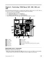
Page 133: ...B Cache DDR3 800 80 W models CTO 13U 13G 03X3645 6 10 Microprocessor Intel Xeon E5606 Quad Core 2 13 GHz 4 8QPI 4 MB Cache DDR3 800 80 W models CTO 03X3646 6 10 Microprocessor Intel Xeon E5607 Quad Core 2 26 GHz 4 8QPI 4 MB Cache DDR3 800 80 W models CTO 03X3647 6 10 Microprocessor Intel Xeon E5645 6 Core 2 4 GHz 5 86QPI 12 MB Cache DDR3 1066 80 W models CTO 03X3648 6 10 Microprocessor Intel Xeon ...

Page 134: ...rive bay models CTO 67Y1424 Lenovo RDX cables models CTO 67Y1425 Lenovo RDX 160 GB cartridge models CTO 67Y1421 Lenovo RDX 320 GB cartridge models CTO 67Y1422 Lenovo RDX 500 GB cartridge models CTO 67Y1423 Documentation DVD 90Y1460 Documentation DVD ML 91Y1652 EasyStartup 03X3602 Windows 2008 SBS SP2 STD 64 bit United Sates models CTO 90Y1174 Windows 2008 SBS SP2 STD 64 bit France models CTO 90Y11...

Page 135: ...ux models CTO 46U3191 3 Optical drive DVD ROM drive 16x 48x SATA with no software DOS Linux models CTO 71Y5543 3 Optical drive DVD burner CD RW SATA with no software DOS Linux models CTO 13U 13G 14G 15U 15G 16U 16G 17U 17G 18U 18G 19U 19G 1AU 1AG 1BU 1BG 46U3206 4 Hard disk drive 250 GB SATA 7200 rpm 3 Gb s 8 MB Cache 3 5 models CTO 46U3100 4 Hard disk drive 500 GB SATA 7200 rpm 3 Gb s 16 MB Cache...

Page 136: ...z 5 86QPI 12 MB Cache DDR3 1066 80 W models CTO 13U 13G 19U 19G 71Y9049 6 10 Microprocessor Intel Xeon E5507 Quad Core 2 26 GHz 4 8QPI 4 MB Cache DDR3 800 80 W models CTO 12U 12G 71Y9031 6 10 Microprocessor Intel Xeon E5603 Quad Core 1 6 GHz 4 8QPI 4 MB Cache DDR3 800 80 W models CTO 15U 15G 03X3645 6 10 Microprocessor Intel Xeon E5606 Quad Core 2 13 GHz 4 8QPI 4 MB Cache DDR3 800 80 W models CTO ...

Page 137: ...Server RAID Technology II models CTO 46U3225 ThinkServer RAID 500 Adapter Raid 5 Controller models CTO 13U 13G 46U3464 ThinkServer RAID 500 Adapter B 2 without RAID 5 models CTO 03X3634 ThinkServer RAID 500 Upgrade Key for Advanced RAID 03X3604 Intel Remote Management Module 3 models CTO 13U 13G 46U3229 Lenovo RDX drive bay models CTO 67Y1424 Lenovo RDX cables models CTO 67Y1425 Lenovo RDX 160 GB ...

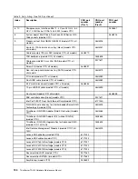
Page 138: ... CRU part number Tier 2 FRU part number 1 Power supply Delta 625 W PSU models CTO all models 46U3201 2 7 Memory module 2 GB DDR3 RDIMM 1333 MHz models CTO 46U3442 2 7 Memory module 4 GB DDR3 RDIMM 1333 MHz models CTO 46U3443 2 7 Memory module 2 GB DDR3 LV RDIMM models CTO 46U3193 3 Optical drive DVD ROM drive 16x 48x SATA with no software DOS Linux models CTO 46U3191 3 Optical drive DVD ROM drive ...

Page 139: ...640 Quad Core 2 66 GHz 5 86QPI 12 MB Cache DDR3 1066 80 W models CTO 71Y9045 6 10 Microprocessor Intel Xeon X5660 6 Core 2 80 GHz 6 4QPI 12 MB Cache DDR3 1333 95 W models CTO 71Y9041 6 10 Microprocessor Intel Xeon X5650 6 Core 2 66 GHz 6 4QPI 12 MB Cache DDR3 1333 95 W models CTO 71Y9043 6 10 Microprocessor Intel Xeon E5630 Quad Core 2 53 GHz 5 86QPI 12 MB Cache DDR3 1066 80 W models CTO 71Y9047 6...

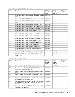
Page 140: ...ls 46U3582 5 25 metal blank bezel models CTO all models 46U3584 12 pin LED SW cable models CTO all models 46U3590 Front panel models CTO all models 46U3588 SAS controller cable Drake models CTO 90Y1611 Intel Pro 1000 PT Dual Port Ethernet Card models CTO 67Y1430 S W RAID 5 activation key for Intel Embedded Server RAID Technology II models CTO 46U3225 ThinkServer RAID 500 Adapter Raid 5 Controller ...

Page 141: ...s CTO 90Y1194 Windows 2008 R2 ENT 64 bit Italy models CTO 90Y1195 Windows 2008 R2 ENT 64 bit Spain models CTO 90Y1197 Windows 2008 SBS SP2 PREM 64 bit United Sates models CTO 90Y1182 Intel Pro 1000 PT dual port Ethernet card models CTO 67Y1430 ThinkServer RAID 500 Adapter B 2 Raid 5 Controller models CTO 03X3635 Table 10 Parts listing Type 1040 Index Description CRU part number Tier 1 CRU part num...

Page 142: ... Xeon L5609 Quad Core 1 86 GHz 5 86QPI 12 MB Cache DDR3 1333 40 W models CTO 46U3187 6 10 Microprocessor Intel Xeon X5670 6 Core 2 93 GHz 6 4QPI 12 MB Cache DDR3 1333 95 W models CTO 71Y9037 6 10 Microprocessor Intel Xeon X5667 Quad Core 3 06 GHz 6 4QPI 12 MB Cache DDR3 1333 95 W models CTO 71Y9039 6 10 Microprocessor Intel Xeon E5640 Quad Core 2 66 GHz 5 86QPI 12 MB Cache DDR3 1066 80 W models CT...

Page 143: ...s 46U3231 Cable assembly 790 mm SATA models CTO all models 46U3570 FRU backplane models CTO all models 03X3605 Cable assembly 880 mm Mini SAS models CTO all models 90Y1611 Screw kit models CTO all models 46U3591 Non hot swap hard disk drive tray SATA models CTO all models 46U3579 I O shield models CTO all models 46U3580 Front USB cable models CTO all models 46U3582 5 25 metal blank bezel models CT...

Page 144: ...aly models CTO 90Y1188 Windows 2008 R2 ENT 64 bit United Sates models CTO 90Y1191 Windows 2008 R2 ENT 64 bit France models CTO 90Y1193 Windows 2008 R2 ENT 64 bit Germany models CTO 90Y1194 Windows 2008 R2 ENT 64 bit Italy models CTO 90Y1195 Windows 2008 R2 ENT 64 bit Spain models CTO 90Y1197 Windows 2008 SBS SP2 PREM 64 bit United Sates models CTO 90Y1182 ThinkServer RAID 500 Adapter B 2 Raid 5 Co...

Page 145: ...20 South Africa models CTO 11G 41R3224 Hong Kong UK Ireland Singapore Malaysia Brunei models CTO 41R3228 Switzerland models CTO 11G 41R3232 Italy models CTO 11G 41R3236 Israel models CTO 11G 41R3256 China models CTO 41R3260 Korea models CTO 41R3270 Brazil models CTO 41R3278 Taiwan models CTO 43N9029 Thailand models CTO Table 12 Power cords Type 1029 Lenovo power cord part number Used in these coun...

Page 146: ...and models CTO 41R3232 Italy models CTO z 41R3236 Israel models CTO 41R3256 China models CTO 41R3260 Korea models CTO 41R3270 Brazil models CTO 41R3278 Taiwan models CTO 43N9029 Thailand models CTO Table 14 Power cords Type 1040 Lenovo power cord part number Used in these countries and regions 41R3176 Argentina Paraguay Uruguay models CTO 41R3184 US models CTO 41R3208 Singapore India Malaysia Thai...

Page 147: ...wer cords Type 1040 continued Lenovo power cord part number Used in these countries and regions 41R3278 Taiwan models CTO 43N9029 Thailand models CTO Chapter 6 Parts listing TD230 Types 1027 1029 1039 and 1040 141 ...

Page 148: ...142 ThinkServer TD230 Hardware Maintenance Manual ...

Page 149: ...fferent server configurations and the applications that are available for configuring and managing RAID arrays Table 15 Server configurations and applications for configuring and managing RAID arrays Server configuration RAID array configuration before operating system is installed RAID array management after operating system is installed INTEL ESRT2 SATA software RAID INTEL ESRT2 Configuration Ut...

Page 150: ...with Do not change the value of unfamiliar items or items that are not mentioned in this manual to avoid any unexpected problems If you cannot turn on the server because of incorrect BIOS settings refer to Jumper block settings on page 35 and use the jumpers to clear CMOS and recover to the factory default settings 2 If you have changed any hardware except the hard disk drives in the server you mu...

Page 151: ...ogram Table 18 Items under the Advanced menu Item Description Processor Configuration Enter the submenu to see all the options See Table 19 Submenus under the Processor Configuration on page 146 Memory Configuration Enter the submenu to see all the options See Table 20 Submenus under the Memory Configuration on page 146 Mass Storage Controller Configuration Enter the submenu to see all the options...

Page 152: ...for Directed I O Disabled Enabled Enable or disable the Intel Virtualization Tech for I O devices Hardware Prefetcher Disabled Enabled Enable or disable the prefetch function of the microprocessor This setting might impact system performance Adjacent Cache Line Prefetch Disabled Enabled Enable or disable the adjacent cache line prefetch This setting might impact system performance Direct Cache Acc...

Page 153: ...e serial port 1 I O address IRQ 3 4 Select the serial port 1 I O interruption Serial B Enable Disabled Enabled Enable or disable the serial port 2 I O Address 3F8 2F8 3E8 2E8 Select the serial port 2 I O address IRQ 3 4 Select the serial port 2 I O interruption Note The settings in are the default settings in the Setup Utility program Table 24 Submenus under the USB Configuration Item Option Descr...

Page 154: ...he Setup Utility program Table 27 Items under the Security menu Item Option Description Set Administrator Password Set or change the administrator password The password can be any combination of up to 7 1 to 7 alphabetic and numeric characters Set User Password Set or change the user password The password can be any combination of up to 7 1 to 7 alphabetic and numeric characters Front Panel Lockou...

Page 155: ...n Delete boot options EFI Optimized Boot Disabled Enabled Boot Option Retry Disabled Enabled Note The settings in are the default settings in the Setup Utility program Exiting the Setup Utility program After you finish viewing or changing settings press Esc to return to the Setup Utility program main menu You might have to press Esc several times Then you can do one of the following If you want to...

Page 156: ...User Password For information about the administrator password and user password see Table 27 Items under the Security menu on page 148 3 Follow the instructions on the screen to set change or delete a password Note A password can be any combination of up to 7 1 to 7 alphabetic and numeric characters For more information see Password considerations on page 150 RAID controllers The following table ...

Page 157: ...he ThinkServer EasyStartup program The ThinkServer EasyStartup DVD simplifies the process of configuring your RAID controllers and installing an operating system The program works in conjunction with your Windows or Linux operating system installation disc to automate the process of installing the operating systems and associated device drivers If you did not receive an ThinkServer EasyStartup DVD...

Page 158: ...ll be presented with the Lenovo License Agreement Read the license agreement carefully You must agree with terms in order to continue After agreeing to the license agreement you will be given the following choices Continue to the main program interface Use a shortcut to install an operating system based a response file that you previously created using the EasyStartup program Use a shortcut to con...

Page 159: ...ition the selected drive or use an existing partition Partition settings This task enables you to choose the file system type and define the partition size Installation settings This task prompts you for user and system settings the operating system product key and the administrator password Network settings This task prompts you for domain and workgroup settings Ethernet controller type IP addres...

Page 160: ...ve and doing related settings The Rebuild item is for rebuilding the RAID volume The Check Consistency item is for consistency check Creating a RAID volume This section provides instructions on how to create a RAID volume by using the Intel Embedded Server RAID Technology II program There are three methods to create a RAID volume Easy Configuration Using all hard disk drives to create a RAID array...

Page 161: ...structions on how to initialize the RAID volume you have created After you create a new RAID volume it is recommended that you initialize the created RAID volume However initializing the RAID volume will delete the data on the selected RAID volume To initialize the RAID volume you have created do the following 1 Do one of the following Select Management Initialize from the main menu and then use t...

Page 162: ...em This function only applies to RAID 1 The controller can only report the inconsistency or report and fix the inconsistency From the main menu select Objects Adapter Chkconstate to set the controller To check the consistency of the RAID 1 volume do the following 1 Select Management Check Consistency from the main menu and press Enter The Check Consistency menu opens 2 Use the space key to select ...

Page 163: ...r the onboard SATA software RAID See Configuring the onboard SATA software RAID on page 153 Configuring the Gigabit Ethernet controller The Ethernet controllers are integrated on the system board They provides an interface for connecting to a 10 Mbps 100 Mbps or 1 Gbps network and provides full duplex FDX capability which enables simultaneous transmission and reception of data on the network If th...

Page 164: ...sc 4 Set the optical drive as the first boot device and insert the disc into the optical drive The server will proceed directly to the User Interface Application s introductory screen 5 Read the messages and instructions displayed on the introductory screen Then click Next to proceed to the list of firmware updates available on the optical media 6 Click Apply to begin the updates click Cancel if y...

Page 165: ...Also the ThinkServer EasyStartup program provides an option to install the ThinkServer EasyManage Agent as part of the operating system installation process Chapter 7 Configuring the server 159 ...

Page 166: ...160 ThinkServer TD230 Hardware Maintenance Manual ...

Page 167: ... Yes Battery charge time 4 hours Auxiliary power Yes Battery life and data retention time This sections includes information about the battery life and data retention time It is recommended that you replace the battery pack on the battery card assembly once a year or after 500 recharging cycles whichever comes first The data retention time for the battery card assembly is as follows BBU name Data ...

Page 168: ...162 ThinkServer TD230 Hardware Maintenance Manual ...

Page 169: ...ograms come with documentation that contains troubleshooting procedures and explanations of error messages and error codes If you suspect a software problem see the documentation for the operating system or program Using the documentation Information about your Lenovo system and preinstalled software if any or optional device is available in the documentation that comes with the product That docum...

Page 170: ...re subject to change without notice If the number for your country or region is not provided contact your Lenovo reseller or Lenovo marketing representative If possible be at your computer when you call Have the following information available Machine type and model Serial numbers of our hardware products Description of the problem Exact wording of any error messages Hardware and software configur...

Page 171: ... apply Purchasing additional services During and after the warranty period you can purchase additional services such as support for hardware operating systems and application programs network setup and configuration upgraded or extended hardware repair services and custom installations Service availability and service name might vary by country or region For more information about these services g...

Page 172: ...166 ThinkServer TD230 Hardware Maintenance Manual ...

Page 173: ...ublication Lenovo may make improvements and or changes in the product s and or the program s described in this publication at any time without notice The products described in this document are not intended for use in implantation or other life support applications where malfunction may result in injury or death to persons The information contained in this document does not affect or change Lenovo...

Page 174: ...ternal hard disk drive capacities assume the replacement of any standard hard disk drives and population of all hard disk drive bays with the largest currently supported drives that are available from Lenovo Maximum memory might require replacement of the standard memory with an optional memory module Lenovo makes no representation or warranties regarding non Lenovo products and services including...

Page 175: ... recovered at end of life Users of EEE with the WEEE marking per Annex IV of the WEEE Directive as shown above must not dispose of end of life EEE as unsorted municipal waste but use the collection framework available to customers for the return recycling and recovery of WEEE Customer participation is important to minimize any potential effects of EEE on the environment and human health due to the...

Page 176: ...can Society of Heating Refrigerating and Air Conditioning Engineers Inc 2 The deliquescent relative humidity of particulate contamination is the relative humidity at which the dust absorbs enough water to become wet and promote ionic conduction 3 ANSI ISA 71 04 1985 Environmental conditions for process measurement and control systems Airborne contaminants Instrument Society of America Research Tri...

Page 177: ... accumulateurs usés Les directives déterminent la marche à suivre en vigueue dans l Union Européenne pour le retour et le recyclage des batteries et accumulateurs usés Cette étiquette est appliquée sur diverses batteries pour indiquer que la batterie ne doit pas être mise au rebut mais plutôt récupérée en fin de cycle de vie selon cette norme In accordance with the European Directive 2006 66 EC ba...

Page 178: ...rmful interference to radio communications Operation of this equipment in a residential area is likely to cause harmful interference in which case the user will be required to correct the interference at his own expense Properly shielded and grounded cables and connectors must be used in order to meet FCC emission limits Lenovo is not responsible for any radio or television interference caused by ...

Page 179: ...g des Gesetzes über die elektromagnetische Verträglichkeit von Betriebsmittein Dieses Produkt entspricht dem Gesetz über die elektromagnetische Verträglichkeit von Betriebsmitteln EMVG früher Gesetz über die elektromagnetische Verträglichkeit von Geräten Dies ist die Umsetzung der EU Richtlinie 2004 108 EG früher 89 336 EWG in der Bundesrepublik Deutschland Zulassungsbescheinigung laut dem Deutsch...

Page 180: ...g des EMVG sicherzustellen sind die Geräte wie in den Handbüchern angegeben zu installieren und zu betreiben Korea Class A compliance statement Japan VCCI Class A compliance statement Japan compliance statement for products which connect to the power mains with rated current less than or equal to 20 A per phase China Class A compliance statement Taiwan Class A compliance statement 174 ThinkServer ...

Page 181: ... hot swap removing 65 DVD drive problems 15 error symptoms 15 E EasyStartup using 151 electronic emission Class A notice 172 error symptoms CD ROM drive DVD ROM drive 15 general 16 hard disk drive 16 intermittent 16 keyboard non USB 17 memory 17 microprocessor 18 monitor 19 mouse non USB 17 optional devices 20 pointing device non USB 17 power 21 serial port 22 software 23 USB port 23 Ethernet cont...

Page 182: ...alling 52 removing 52 K keyboard problems 17 L LEDs rear of the server 30 LEDs and controls on the front of the server 27 locating connectors backplane 37 logs system event message 25 M memory module installation order 49 installation rules 49 installing 50 removing 51 memory modules specifications 12 memory problems 17 microprocessor installing 111 problems 18 removing 110 specifications 12 minim...

Page 183: ...lling 82 removing 86 S SAS or SATA hot swap hard disk drive installing 60 SAS or SATA hot swap hard disk drives removing 57 SAS or SATA non hot swap hard disk drives removing 65 serial port problems 22 server turn off 124 turn on 123 server components locating parts 32 server configuration updating 143 server cover installing 122 removing 43 server cover reinstalling 122 serviceability 12 Setup Ut...

Page 184: ...dating firmware 158 updating the server configuration 123 USB port problems 23 using EasyStartup 151 passwords 149 Setup Utility program 143 V video problems 19 video controller integrated specifications 12 W Web site compatible options 49 Lenovo support 39 publication ordering 163 support 163 working inside the server with the power on 41 178 ThinkServer TD230 Hardware Maintenance Manual ...

Page 185: ......

Page 186: ...Part Number Printed in China 1P P N ...

Reviews: