


5.
Disconnect the signal cable and the power cable from the hard disk drive.
6.
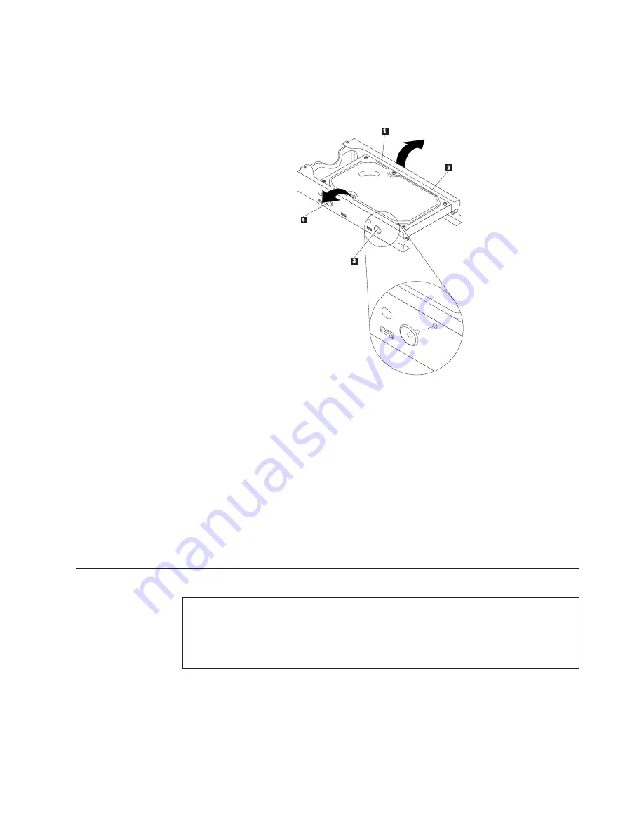
Remove the old hard disk drive from the bracket by flexing the sides of the
bracket enough to slide it free from the hard disk drive.
7.
To install a new hard disk drive into the bracket, flex the bracket and align
pin
1
, pin
2
, pin
3
, and pin
4
on the bracket with the holes in the
hard disk drive.
Important:
Do not touch the circuit board on the bottom of the hard disk
drive.
8.
Connect the signal cable and the power cable to the new hard disk drive.
9.
Install the new hard disk drive and bracket into the rear retainer and rotate
down until the two clips on the blue handle of the hard disk drive bracket
snap into position.
10.
Go to “Completing the FRU replacement” on page 155.
Replacing the optical drive
Attention
Do not open your computer or attempt any repair before reading and understanding the
“Important safety information” in the
ThinkCentre Safety and Warranty Guide
that came with
your computer. To obtain a copy of the
ThinkCentre Safety and Warranty Guide
, go to:
http://www.lenovo.com/support
This section provides instructions on how to replace the optical drive.
To replace the optical drive:
1.
Open the computer cover. See “Opening the computer cover” on page 126.
2.
Pivot the drive bay assembly upward to gain access to the optical drive. See
“Accessing the system board components and drives” on page 127.
Figure 53. Removing the hard disk drive from the bracket
Chapter 9. Replacing FRUs - 607
137
Summary of Contents for 7515L2U
Page 2: ......
Page 3: ...ThinkCentre Hardware Maintenance Manual ...
Page 17: ...Chapter 2 Safety information 11 ...
Page 18: ...12 Hardware Maintenance Manual ...
Page 19: ... 18 kg 37 lbs 32 kg 70 5 lbs 55 kg 121 2 lbs 1 2 Chapter 2 Safety information 13 ...
Page 23: ...Chapter 2 Safety information 17 ...
Page 24: ...1 2 18 Hardware Maintenance Manual ...
Page 25: ...Chapter 2 Safety information 19 ...
Page 26: ...1 2 20 Hardware Maintenance Manual ...
Page 33: ...Chapter 2 Safety information 27 ...
Page 34: ...28 Hardware Maintenance Manual ...
Page 35: ...1 2 Chapter 2 Safety information 29 ...
Page 39: ...Chapter 2 Safety information 33 ...
Page 40: ...1 2 34 Hardware Maintenance Manual ...
Page 44: ...38 Hardware Maintenance Manual ...
Page 48: ...42 Hardware Maintenance Manual ...
Page 56: ...50 Hardware Maintenance Manual ...
Page 128: ...122 Hardware Maintenance Manual ...
Page 291: ......
Page 292: ...Part Number 53Y6319 Printed in USA 1P P N 53Y6319 ...


