


4.
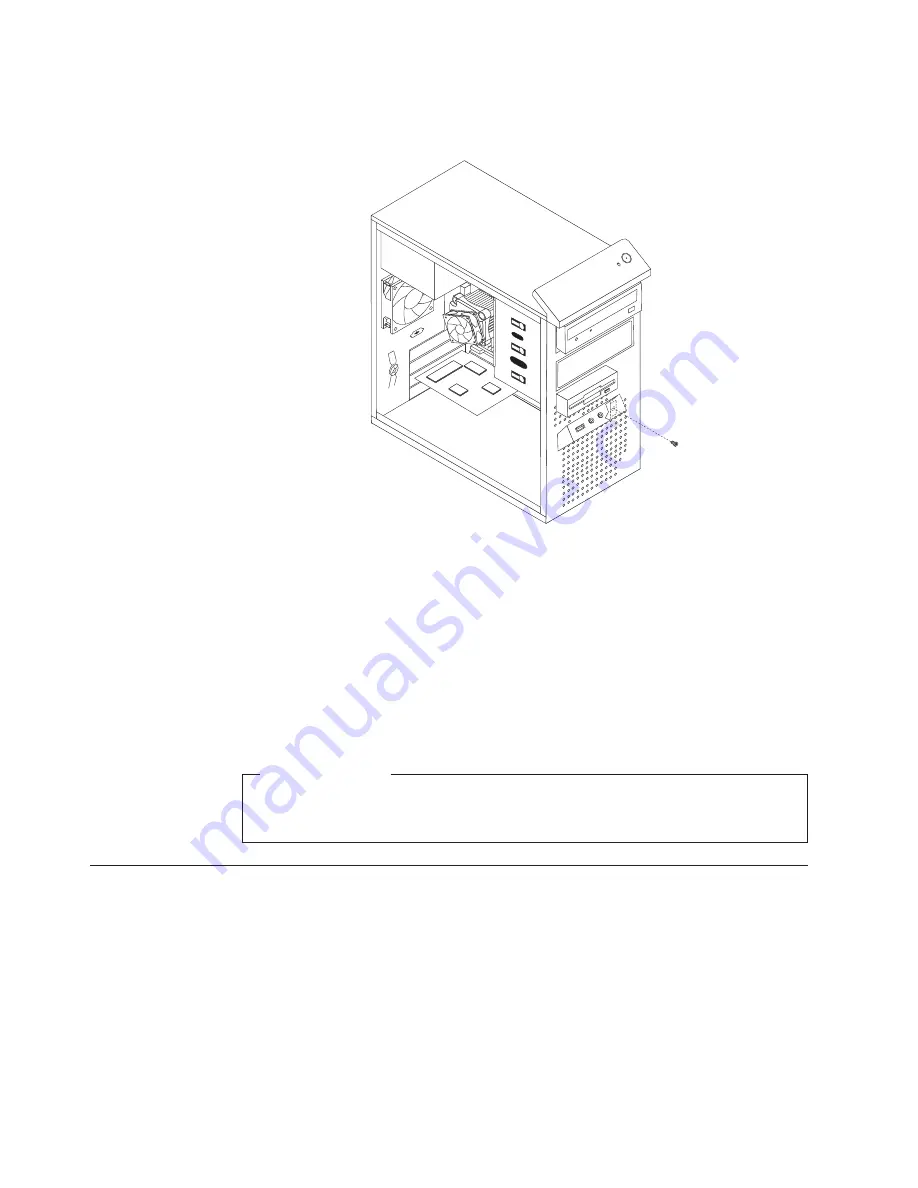
Note the front audio and USB assembly cables routing and remove the screw
that secures the front audio and USB assembly to the chassis.
5.
Remove the front audio and USB assembly.
6.
Route the cables for the new front audio and USB assembly through the hole in
the chassis to the system board.
7.
Install the new front audio and USB assembly into the chassis and secure it
with the screw.
8.
Connect the new front audio and USB assembly cables to the system board. See
“Locating parts on the system board” on page 89.
9.
Reinstall the front bezel.
What to do next:
v
To work with another piece of hardware, go to the appropriate section.
v
To complete the replacement, go to “Completing the FRU replacement.”
Completing the FRU replacement
After replacing the FRUs, you need to reinstall any removed parts, reconnect and
route any internal cables, reinstall the computer cover, and reconnect any external
cables, including telephone lines and power cords. Depending on the FRUs
replaced, you might need to confirm the updated information in the Setup Utility
program, see Chapter 6, “Using the Setup Utility program,” on page 51.
Note:
When the power cord is first plugged in, the computer might appear to turn
on for a few seconds and then turn off. This is a normal sequence to enable
the computer to initialize.
To reinstall the computer cover and reconnect cables to your computer:
Figure 37. Removing the front audio and USB assembly
120
Hardware Maintenance Manual
Summary of Contents for 7515L2U
Page 2: ......
Page 3: ...ThinkCentre Hardware Maintenance Manual ...
Page 17: ...Chapter 2 Safety information 11 ...
Page 18: ...12 Hardware Maintenance Manual ...
Page 19: ... 18 kg 37 lbs 32 kg 70 5 lbs 55 kg 121 2 lbs 1 2 Chapter 2 Safety information 13 ...
Page 23: ...Chapter 2 Safety information 17 ...
Page 24: ...1 2 18 Hardware Maintenance Manual ...
Page 25: ...Chapter 2 Safety information 19 ...
Page 26: ...1 2 20 Hardware Maintenance Manual ...
Page 33: ...Chapter 2 Safety information 27 ...
Page 34: ...28 Hardware Maintenance Manual ...
Page 35: ...1 2 Chapter 2 Safety information 29 ...
Page 39: ...Chapter 2 Safety information 33 ...
Page 40: ...1 2 34 Hardware Maintenance Manual ...
Page 44: ...38 Hardware Maintenance Manual ...
Page 48: ...42 Hardware Maintenance Manual ...
Page 56: ...50 Hardware Maintenance Manual ...
Page 128: ...122 Hardware Maintenance Manual ...
Page 291: ......
Page 292: ...Part Number 53Y6319 Printed in USA 1P P N 53Y6319 ...


