background image

9

NOTE: DIAGRAMS & ILLUSTRATIONS ARE NOT TO SCALE.

B. Reach under the bottom front of the front 

glass enclosure and pull it forward as shown 
in 

Figure 7

.

Figure 7

C.  Lift glass assembly up and out and carefully 

set aside in a safe place (see 

Figure 8

).

Figure 8

Remove Cardboard

Figure 9

Step 6: REMOVE CARDBOARD 

-  Remove the 

cardboard packaging material from beneath 
the relief door and discard (see 

Figure 9

).

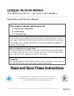
Wiring - Optional Forced Air Blower Kit:

BK-CI (see 

Figure 11

 for wiring diagram) -  (An 

optional fi eld-provided outletbox/J-Box may 
also be used). Install the blower kit according 
to the installation instructions provided with 
the kit.

Figure 11

Blower
Mounting 
Bracket

Black

Black

White

White

Fan Disc

  Rheostat

Blower
Assembly 
(Shown 
Rotated 90 
Degrees CCW)

Black

Power Cord

A. Optional accessories include a wall ther-

mostat, blower kit, brick liner kit, warming 
shelves and a standard or deluxe remote 
control kits. 

B. If a wall-mounted thermostat is selected, 

mount it in a convenient location on a wall 
near the stove. If the warming shelves are 
being installed, see Homeowners Manual 
for installation instructions.

C. Wire the thermostat within the millivolt control 

circuit using a maximum of 25 feet of 18 gage, 
2 conductor wire. Caution: Do not connect the 
optional wall thermostat, gas control valve 
or control wiring system of the unit to a 120 
volt power supply (residential line voltage) 

The gas valve is set in place and pre-wired at the 
factory on both models (see

 Figure 11

).

       SIT Millivolt Wiring Diagram

If any of the original wire as supplied must be replaced,
it must be replaced with


Type AWM105

°

C – 18 GA. wire.

Thermopile

TH

TP

TH

TP

* ON/OFF Switch, Optional 
   Thermostat Remote 
   Control Receiver 
   

* SWITCH

Figure 10

Blower Wiring Diagram

RELIEF DOOR

Step 5: REMOVE MATERIALS FROM FIRE-

BOX 

-  Remove the packaged materials from 

inside of the fi rebox and set aside (propane 
conversion kit, log support cartons, log set 
and embers).


IMPORTANT

Ground supply lead must be con-
nected to the wire attached to the 
green ground screw located on the  
outlet box.  See 

Figure 47

. Failure to 

do so will result in a potential  safety 
hazard.  The appliance must be 
electrically grounded in accordance 
with local codes or, in the absence of 
local codes, the National Electrical 
Code, ANSI/NFPA 70-latest edition. 
(In Canada, the current CSA C22-1 
Canadian Electrical Code).


WARNING

The power cord must be plugged 
directly into a properly grounded 
three-prong 120 volt, 60 hz wall 
receptacle. Do not cut or remove 
the grounding prong from this plug.  
Do not route power cord under or 
in front of appliance.

Step 7: INSTALL LP CONVERSION KIT 
(IF NECESSARY) AND OPTIONAL ACCES-
SORIES 

Install the LP conversion kit and optional 
accessories per instructions provided with 
the kits (do not install an optional fi rescreen 
or brick liner kit at this point).

Summary of Contents for SEREFINA CI1500DVF series

Page 1: ...E OU LA MORT POUR VOTRE SÉCURITÉ Ne pas entreposer ni utiliser d essencenid autrevapeursouliquidesinflammablesdans le voisinage de cet appareil ou de tout autre appareil POUR VOTRE SÉCURITÉ Que faire si vous sentez une odeur de gaz Ne pas tenter d allumer d appareil Ne touchez à aucun interrupteur Ne pas vous servir des téléphones se trouvant dans le batiment où vous vous trouvez Evacuez la piéce ...

Page 2: ...used Millivolt appliances are designed to oper ate on natural or propane gas A millivolt gas control valve with piezo ignition system provides safe efficient operation External electrical power is required to operate the optional blower if installed on these units Note Installation and repair should be per formed by a qualified service person The appliance should be inspected annually by a qualifi...

Page 3: ...e appliances and their individual shut off valves must be disconnected from the gas supply piping system during any pressure testing of that system at pressures in excess of 1 2 psig 3 5 kPa These appliances must be isolated from the gas supply piping system by closing their individual manual shut off valve during any pressure testing of the gas supply piping system at test pressures equal to or l...

Page 4: ...mm H 40 1016 mm 48 1 2 1232 mm Specifications CI1500DVF CI2500DVF Min Max BTU hr Input NG 17 500 28 000 25 500 38 500 Min Max BTU hr Input LP 20 500 27 000 26 500 34 500 DV Vent Size 4 inner 6 5 8 outer 4 inner 6 5 8 outer Room Fan CFM 150 150 Weight lb 206 290 Efficiencies CI1500DVF CI2500DVF EnerGuide P4 67 NG 65 LP 67 NG 64 LP Steady State Efficiency 85 NG 87 LP 83 NG 85 LP Note Due to Lennox o...

Page 5: ... alcove that allows for the minimum clearances to combustible surfaces Your local building inspector should review your plans prior to installation When installing this appliance provide adequate clearances for the purposes of servicing and proper operation As determined through the safety certification of this unit a minimum clearance to combustible materials must be maintained around specific ar...

Page 6: ...additionalvent location restrictions refer to Figure 5 VENT TERMINATION CLEARANCES Vertical Vent Termination Clearances These instructions should be used as a guidelineanddonotsupersedelocalcodesin anyway Installventaccordingtolocalcodes these instructions the current National Fuel Gas Code ANSI Z223 1 in the USA or the current standards of CAN CGA B149 1 and B149 2 in Canada Side Elevation View Q...

Page 7: ... n i w t n e v e r p o t d e d n e m m o c e r m m 9 2 2 9 n o i t a s n e d n o c w o d n i w t i f f o s d e t a l i t n e v o t e c n a r a e l c l a c i t r e V D l a t n o z i r o h a n i h t i w l a n i m r e t e h t e v o b a d e t a c o l r e t n e c e h t m o r f m m 8 5 4 s e h c n i 8 1 f o e c n a t s i d l a n i m r e t e h t f o e n i l m m 8 5 4 8 1 m m 8 5 4 8 1 t i f f o s d e t a...

Page 8: ...et aside Step5 Page8 Removepackagedmaterials from inside firebox and set aside log set bag of embers and NG to LP conversion kit Step 6 Page 9 Remove cardboard packag ing material from beneath relief door and discard Step 7 Page 9 Install LP Conversion kit if necessary Install any optional accessories excluding firescreens Step 8 Page 9 Install lower access door Step 9 Page 9 Venting System Instal...

Page 9: ...control wiring system of the unit to a 120 volt power supply residential line voltage Thegasvalveissetinplaceandpre wiredatthe factory on both models see Figure 11 SIT Millivolt Wiring Diagram If any of the original wire as supplied must be replaced it must be replaced with Type AWM105 C 18 GA wire Thermopile TH TP TH TP ON OFF Switch Optional Thermostat Remote Control Receiver SWITCH Figure 10 Bl...

Page 10: ...see Figures 13 and 14 SupportBrackets Installventsupportbrack ets as specified in the vent manufacturers instructions and the National Gas Fuel Code USA NFPA 54 ANSI Z223 1 7 6 5 Support ofGasVents Gasventsshallbesupportedand spaced in accordance with their listings and the vent manufacturer instructions General Information These instructions should be used as a guideline and do not supersedelocal...

Page 11: ...ance for Natural Gas and 36 for Propane Gas before the first elbow The horizontal run may extend up to 20 feet 6 meters and include a vertical rise of up to 40 feet 12 meters see Figure 13 Horizontal termination must meet the criteria shown in Figures 4 and 5 Approved vent systems must terminate above and including the heavy line in Figure 13 Two 45 degree elbows may be substituted for each single...

Page 12: ...nversion Kit for 6 I D 1 insulation SV4CCK2 Factory Built Chimney Conversion Kit for 7 I D 1 insulation 8 I D 1 insulation 6 I D 2 insulation SV4CCK3 Factory Built Chimney Conversion Kit for 10 I D 1 insulation 7 I D 2 insulation 8 I D 2 insulation Model Brand SIMPSON DURA VENT Description 934 Masonry Chimney Conversion Kit 931 Factory Built Chimney Conversion Kit A for 6 I D 932 Factory Built Chi...

Page 13: ...Black 904B 24 Pipe Length Black SV4L36 36 Pipe Length Galvanized 903 36 Pipe Length Galvanized SV4LB36 36 Pipe Length Black 903B 36 Pipe Length Black SV4L48 48 Pipe Length Galvanized 902 48 Pipe Length Galvanized SV4LB48 48 Pipe Length Black 902B 48 Pipe Length Black SV4LA 6 Adj Pipe Length Galvanized 908 6 Adj Pipe Length Galvanized SV4LBA 6 Adj Pipe Length Black N A N A SV4LA12 12 Adj Pipe Lengt...

Page 14: ...inlet port fitting Figure 20 Ember Strip Rear Log Figure 21 Left Front Log Figure 22 2 Place the largest log onto the rear log stoppers see Figure 20 Ensure that the grooves on the bottom of the log aligns onto the corresponding places on the rear log stoppers Push the log back so that it is against the back of the rear log stoppers see Figure 21 3 Place the left front log onto the corre sponding ...

Page 15: ...ethefineembermaterial mineral wool into dime sized fluffy pieces b Distribute the pieces over the top of the front burner ports avoiding covering the slots see Figure 29 and filling the area in front of the forward logs Figure 26 Figure 27 Figure 29 VERIFY THAT THE GAS LINE HAS BEEN PURGED OF AIR SEE STEP 10 Figure 25 Left Top Twig Step 12 RE INSTALL FRONT GLASS ENCLOSURE PANEL Reverse instruction...

Page 16: ...d run initial system checkout before closing up the front of the unit Follow the pilot lighting instruc tions provided in the Homeowner s Care and Operation Instructions or pull out the instruction label located in a holder on rear shield of stove For piezo igniter location see Figure 30 Fasten the two latches located beneath the firebox floor to the glass frame vee flange Close both the latches s...

Page 17: ...15 9 mm CI2500DVF 1 2 12 7 mm 5 8 15 9 mm Initially always position the air shutter to the factorysettingasshowninFigure34 adjust mentrodislocatedinthelowercontrolarea This can be done by moving the adjustment rodupordownaccordingly Allowtheburner to operate for at least 15 minutes Observe the flame continuously If it appears weak or sooty as previously described adjust the air shutter to a more o...

Page 18: ...MBRE DE SERIE XXXXX XXXXX IIIIIIIIIIIIIIIIIIII XXXXXXXXXXXXXXXX P N 9 1452A MODEL NO CI1500DVF SERIES MANUFACTURED AT SANTA TERESA NM FOR USE WITH NATURAL GAS EQUIPE POUR GAZ NATUREL ALTITUDE MIN GAS SUPPLY PRESS WC PRESS MIN D ALIMENTATION CE MANIFOLD PRESSURE WC PRESSION CE TUBULURE CE MANUFACTURER S RECOMMENDED ORIFICE SIZE DIMENSION DE L INJECTEUR RECOMMANDE PAR MANUFACTURIER DMS MAX INPUT BTU...

Page 19: ...19 NOTE DIAGRAMS ILLUSTRATIONS ARE NOT TO SCALE ...

Page 20: ...ts P N 775 147M REV D 11 2006 1110 West Taft Avenue Orange CA 92865 Lennox reserves the right to make changes at any time without notice in design materials specifications prices and also to discontinue colors styles and products Consult your local distributor for fireplace code information ...

Reviews: