background image

17

NOTE: DIAGRAMS & ILLUSTRATIONS ARE NOT TO SCALE.

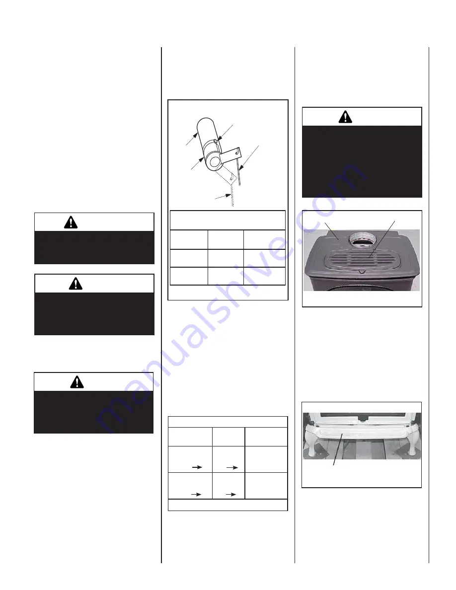
Ref. Air shutter Patent:
U.S. Pat. 5,553,603

Figure 34

Adjustment Rod Up

(1/8" Open Position)

Air Shutter

Burner Tube

Adjusting Set Screw

Adjustment Rod Down

(full open position)

Burner Air Shutter Adjustment

Stove Cast Iron Top

Trivet

Ash Lip


 CAUTION 

The cast iron stove top is very 
heavy and may require a mini-
mum of two people to lift; one 
person on each side (the CI1500 
series cast top weighs ~20 
pounds and the CI2500 series 
cast top weighs ~40 pounds).


 IMPORTANT 

Ensure that the front glass panel 
is in place and sealed during 
adjustment.


 WARNING 

Air shutter adjustment should 
only be performed by a qualifi ed 
professional service techni-
cian.


 CAUTION 

The adjustment rod and nearby 
appliance surfaces are hot. Exer-
cise caution to avoid injury while 
adjusting fl ame appearance.

Burner Adjustment

Air Shutter Adjustment Guidelines: 

If the burner flame appearance differs 
greatly from what is shown on this Page  
(see 

Figure 33

)

, some adjustment from 

standard for the air shutter gap may be 
necessary (to compensate for variables in 
the installation and fuel such as, BTU value 
/ composition, gas pressure, specifi c gravity 
of gas, altitude, etc.).

The following chart is provided to aid you in 
achieving the correct air shutter adjustment 
for your installation.

Air Shutter Adjustment Guidelines:

Amount of 

Primary Air

Flame 

Color

Air Shutter

Adjustment

If air shutter is 
closed too far 

Flame will 
be yellow

Air shutter 
gap should be 
increased

If air shutter is 
open too far 

Flame will 
be blue

Air shutter 
gap should be 
decreased

Table 10

When satisfi ed that the appliance operates 
properly, proceed to fi nish the installation. 
Leave the control knob in the ON position and 
the on/off switch in the OFF position. 

Main Burner Factory Air Shutter 

Opening Setting  - Inches (millimeter)

Model

Natural

Gas

Propane

Gas

CI1500DVF

5/16"

(7.93 mm)

5/8"

(15.9 mm)

CI2500DVF

1/2"

(12.7 mm)

5/8"

(15.9 mm)

Initially, always position the air shutter to the 
factory setting as shown in

 Figure 34

 (adjust-

ment rod is located in the lower control area).  
This can be done by moving the adjustment 
rod up or down accordingly.  Allow the burner 
to operate for at least 15 minutes. Observe 
the fl ame continuously. If it appears weak 
or sooty as previously described, adjust the 
air shutter to a more open position until the 
desired fl ame appearance is achieved.

The adjustment rod and associated adjustable 
air shutter is patented technology. Flame adjust-
ments can be made quickly and accurately to 
taste without the need of disassembling the 
appliance and waiting for 30 minutes after 
each adjustment.

Sooting is indicated by black puffs developing 
at the tips of very long orange fl ames. Sooting 
results in black deposits forming on the logs, 
appliance inside surfaces and on exterior 
surfaces adjacent to the vent termination. 
Sooting is caused by incomplete combus-
tion in the fl ames and lack of combustion air 
entering the air shutter opening. To achieve 
a warm yellow to orange fl ame that does not 
soot, the shutter opening must be adjusted 
between these two extremes.

No smoke or soot should be present. Repo-
sition the logs if fl ames impinge on any of 
them. If the logs are properly positioned 
and sooting conditions exist, the air shutter 
opening on the main burner tube should be 
adjusted. Normally, the more offsets in the 
vent system, the greater the need for the air 
shutter to be opened further. 


Step 16.  INSTALL STOVE TOP, TRIVET 
AND ASH LIP

A. Place the cast iron top into position on the 

stove top (See 

Figure 35

).

  Place the trivet 

into the recess on the cast iron top (See 

Figure 35

).

Figure 35

Figure 36

B. Locate the 

ash lip

 from packaging (Step 2). 

Remove the 2 bolts from the tapped holes in 
the ash lip. Align the ash lip below the fi rebox 
as shown in 

Figure 36

 (the tapped holes 

in ash lip should align with corresponding 
slots below fi rebox).  Reinstall the 2 bolts 
that were removed from the ash lip (fi nger 
tight only. If a tool is used, be careful not to 
overtighten).

Summary of Contents for SEREFINA CI1500DVF series

Page 1: ...E OU LA MORT POUR VOTRE SÉCURITÉ Ne pas entreposer ni utiliser d essencenid autrevapeursouliquidesinflammablesdans le voisinage de cet appareil ou de tout autre appareil POUR VOTRE SÉCURITÉ Que faire si vous sentez une odeur de gaz Ne pas tenter d allumer d appareil Ne touchez à aucun interrupteur Ne pas vous servir des téléphones se trouvant dans le batiment où vous vous trouvez Evacuez la piéce ...

Page 2: ...used Millivolt appliances are designed to oper ate on natural or propane gas A millivolt gas control valve with piezo ignition system provides safe efficient operation External electrical power is required to operate the optional blower if installed on these units Note Installation and repair should be per formed by a qualified service person The appliance should be inspected annually by a qualifi...

Page 3: ...e appliances and their individual shut off valves must be disconnected from the gas supply piping system during any pressure testing of that system at pressures in excess of 1 2 psig 3 5 kPa These appliances must be isolated from the gas supply piping system by closing their individual manual shut off valve during any pressure testing of the gas supply piping system at test pressures equal to or l...

Page 4: ...mm H 40 1016 mm 48 1 2 1232 mm Specifications CI1500DVF CI2500DVF Min Max BTU hr Input NG 17 500 28 000 25 500 38 500 Min Max BTU hr Input LP 20 500 27 000 26 500 34 500 DV Vent Size 4 inner 6 5 8 outer 4 inner 6 5 8 outer Room Fan CFM 150 150 Weight lb 206 290 Efficiencies CI1500DVF CI2500DVF EnerGuide P4 67 NG 65 LP 67 NG 64 LP Steady State Efficiency 85 NG 87 LP 83 NG 85 LP Note Due to Lennox o...

Page 5: ... alcove that allows for the minimum clearances to combustible surfaces Your local building inspector should review your plans prior to installation When installing this appliance provide adequate clearances for the purposes of servicing and proper operation As determined through the safety certification of this unit a minimum clearance to combustible materials must be maintained around specific ar...

Page 6: ...additionalvent location restrictions refer to Figure 5 VENT TERMINATION CLEARANCES Vertical Vent Termination Clearances These instructions should be used as a guidelineanddonotsupersedelocalcodesin anyway Installventaccordingtolocalcodes these instructions the current National Fuel Gas Code ANSI Z223 1 in the USA or the current standards of CAN CGA B149 1 and B149 2 in Canada Side Elevation View Q...

Page 7: ... n i w t n e v e r p o t d e d n e m m o c e r m m 9 2 2 9 n o i t a s n e d n o c w o d n i w t i f f o s d e t a l i t n e v o t e c n a r a e l c l a c i t r e V D l a t n o z i r o h a n i h t i w l a n i m r e t e h t e v o b a d e t a c o l r e t n e c e h t m o r f m m 8 5 4 s e h c n i 8 1 f o e c n a t s i d l a n i m r e t e h t f o e n i l m m 8 5 4 8 1 m m 8 5 4 8 1 t i f f o s d e t a...

Page 8: ...et aside Step5 Page8 Removepackagedmaterials from inside firebox and set aside log set bag of embers and NG to LP conversion kit Step 6 Page 9 Remove cardboard packag ing material from beneath relief door and discard Step 7 Page 9 Install LP Conversion kit if necessary Install any optional accessories excluding firescreens Step 8 Page 9 Install lower access door Step 9 Page 9 Venting System Instal...

Page 9: ...control wiring system of the unit to a 120 volt power supply residential line voltage Thegasvalveissetinplaceandpre wiredatthe factory on both models see Figure 11 SIT Millivolt Wiring Diagram If any of the original wire as supplied must be replaced it must be replaced with Type AWM105 C 18 GA wire Thermopile TH TP TH TP ON OFF Switch Optional Thermostat Remote Control Receiver SWITCH Figure 10 Bl...

Page 10: ...see Figures 13 and 14 SupportBrackets Installventsupportbrack ets as specified in the vent manufacturers instructions and the National Gas Fuel Code USA NFPA 54 ANSI Z223 1 7 6 5 Support ofGasVents Gasventsshallbesupportedand spaced in accordance with their listings and the vent manufacturer instructions General Information These instructions should be used as a guideline and do not supersedelocal...

Page 11: ...ance for Natural Gas and 36 for Propane Gas before the first elbow The horizontal run may extend up to 20 feet 6 meters and include a vertical rise of up to 40 feet 12 meters see Figure 13 Horizontal termination must meet the criteria shown in Figures 4 and 5 Approved vent systems must terminate above and including the heavy line in Figure 13 Two 45 degree elbows may be substituted for each single...

Page 12: ...nversion Kit for 6 I D 1 insulation SV4CCK2 Factory Built Chimney Conversion Kit for 7 I D 1 insulation 8 I D 1 insulation 6 I D 2 insulation SV4CCK3 Factory Built Chimney Conversion Kit for 10 I D 1 insulation 7 I D 2 insulation 8 I D 2 insulation Model Brand SIMPSON DURA VENT Description 934 Masonry Chimney Conversion Kit 931 Factory Built Chimney Conversion Kit A for 6 I D 932 Factory Built Chi...

Page 13: ...Black 904B 24 Pipe Length Black SV4L36 36 Pipe Length Galvanized 903 36 Pipe Length Galvanized SV4LB36 36 Pipe Length Black 903B 36 Pipe Length Black SV4L48 48 Pipe Length Galvanized 902 48 Pipe Length Galvanized SV4LB48 48 Pipe Length Black 902B 48 Pipe Length Black SV4LA 6 Adj Pipe Length Galvanized 908 6 Adj Pipe Length Galvanized SV4LBA 6 Adj Pipe Length Black N A N A SV4LA12 12 Adj Pipe Lengt...

Page 14: ...inlet port fitting Figure 20 Ember Strip Rear Log Figure 21 Left Front Log Figure 22 2 Place the largest log onto the rear log stoppers see Figure 20 Ensure that the grooves on the bottom of the log aligns onto the corresponding places on the rear log stoppers Push the log back so that it is against the back of the rear log stoppers see Figure 21 3 Place the left front log onto the corre sponding ...

Page 15: ...ethefineembermaterial mineral wool into dime sized fluffy pieces b Distribute the pieces over the top of the front burner ports avoiding covering the slots see Figure 29 and filling the area in front of the forward logs Figure 26 Figure 27 Figure 29 VERIFY THAT THE GAS LINE HAS BEEN PURGED OF AIR SEE STEP 10 Figure 25 Left Top Twig Step 12 RE INSTALL FRONT GLASS ENCLOSURE PANEL Reverse instruction...

Page 16: ...d run initial system checkout before closing up the front of the unit Follow the pilot lighting instruc tions provided in the Homeowner s Care and Operation Instructions or pull out the instruction label located in a holder on rear shield of stove For piezo igniter location see Figure 30 Fasten the two latches located beneath the firebox floor to the glass frame vee flange Close both the latches s...

Page 17: ...15 9 mm CI2500DVF 1 2 12 7 mm 5 8 15 9 mm Initially always position the air shutter to the factorysettingasshowninFigure34 adjust mentrodislocatedinthelowercontrolarea This can be done by moving the adjustment rodupordownaccordingly Allowtheburner to operate for at least 15 minutes Observe the flame continuously If it appears weak or sooty as previously described adjust the air shutter to a more o...

Page 18: ...MBRE DE SERIE XXXXX XXXXX IIIIIIIIIIIIIIIIIIII XXXXXXXXXXXXXXXX P N 9 1452A MODEL NO CI1500DVF SERIES MANUFACTURED AT SANTA TERESA NM FOR USE WITH NATURAL GAS EQUIPE POUR GAZ NATUREL ALTITUDE MIN GAS SUPPLY PRESS WC PRESS MIN D ALIMENTATION CE MANIFOLD PRESSURE WC PRESSION CE TUBULURE CE MANUFACTURER S RECOMMENDED ORIFICE SIZE DIMENSION DE L INJECTEUR RECOMMANDE PAR MANUFACTURIER DMS MAX INPUT BTU...

Page 19: ...19 NOTE DIAGRAMS ILLUSTRATIONS ARE NOT TO SCALE ...

Page 20: ...ts P N 775 147M REV D 11 2006 1110 West Taft Avenue Orange CA 92865 Lennox reserves the right to make changes at any time without notice in design materials specifications prices and also to discontinue colors styles and products Consult your local distributor for fireplace code information ...

Reviews: