background image

Page 38 Operating Manual Leica EM TXP 10/10 

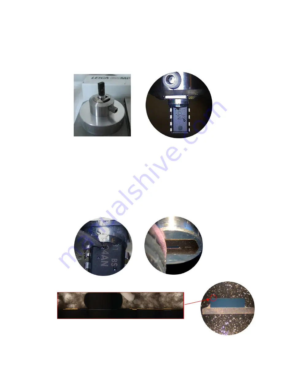
  Flatten the surface of the SEM stub or rod using the tungsten carbide miller. 

The prepared surface is perpendicular to the tool axis. 

  Remove the holder (keep in mind the orientation of the holder). 

  Glue the sample with the polished side down onto the surface of the rod. In 

this case “crystal bond” wax was used. Make sure that the side of the stub or 
rod is not covered with a layer of glue 


  Insert sample into the instrument 

  Insert disc cutter and advance the disc cutter until the front face of the disc 

cutter gently touches the “glue free” part of the stub or rod. 

  Clear the advance indication. 

  Retract the spindle to the desired value (in this case 80µm) and cut the 

sample through. 

  Exchange disc cutter with the polishing inserts (9µm, 6µm, 3µm, and 1µm 

(and 0.5µm). Polish down the sample until the desired value is indicated. 
Take into account the layer thickness of the glue which reduces the actual 
thickness of the sample. Use the HOLD function when replacing the tool 
(foils) 


20µm slice of a gold wire bonding on IC with conductive layers 


Summary of Contents for EM TXP

Page 1: ...Leica EM TXP Operating Manual Version 16214032 10 2010...

Page 2: ...ring techniques used to provide our customers with excellent products Any copyrights of this document are retained by Leica Mikrosysteme GmbH Vienna Any reproduction of text and illustrations or any p...

Page 3: ...nual Leica EM TXP Serial Number Date of purchase For the instrument serial number please refer to the name type label on the back of the instrument Please read this instruction manual carefully before...

Page 4: ......

Page 5: ...Angle adjustment adaptor optional 13 4 10 Inserting the specimen holder 13 4 11 Installing the lubricant cooling system 14 4 12 Attaching the polishing foil onto the carrier 15 5 Description of the co...

Page 6: ...ng 37 9 3 2 Back face slicing 37 10 Useful hints 39 10 1 Recommended sample size 39 10 2 Diamond disc cutter 39 10 3 Diamond miller 39 10 3 1Surfacing of ductile materials and hard polymers 39 10 4 Sa...

Page 7: ...Page 3 Operating Manual Leica EM TXP 10 10 Symbols in this manual and their meaning Attention take extra care Important information...

Page 8: ...chanism initialises and the instrument is ready for use The miller is shielded by a protective cover allowing the miller to operate only when it is closed The user must not make any manipulation in th...

Page 9: ...r 4 control panel 5 top light ring illuminator 6 protective cover 7 tool control lever E W movement 7 1 lever for auto E W movement 8 lubricant cooling system 9 adjustment mechanism 10 hose connection...

Page 10: ...one without removing the sample The EM TXP is a preparation unit with variable speed from 300 to 20 000 rpm with an integrated stereo microscope and ring LED illuminator A pivot arm and adjustment ass...

Page 11: ...ereo microscope and accessories Unfold the lateral wall 2 and remove plate 3 Two persons should lift the instrument out of the box using carton handles 4 Place the instrument on the working table Remo...

Page 12: ...ring illuminator onto the objective mounting of the stereo microscope Clamp the illuminator with attached screw 4 2 2 If the instrument is equipped with M80 with objective adaptor Screw in the object...

Page 13: ...p light ring illuminator onto the objective mounting of the stereo microscope Clamp the illuminator with attached screw Place the ergo wedge and the binocular tube onto the M80 carrier The movable obj...

Page 14: ...estroy the instrument Other vacuum cleaners have to be connected directly to the wall outlets 4 4 Connection of the extraction and filtration unit supplied by Leica Connect the mains cord of the extra...

Page 15: ...ibility of the sample To maintain its brightness keep the illumination foil clean It can be removed for cleaning if necessary Reinstall the illuminator 5 1 with the black pins of the safety cover inse...

Page 16: ...m titanium and zirconium as it will result in the cutting edge wearing out very quickly 4 7 Inserting the cut off wheel or arbor for polishing foil carrier Remove the transparent protective cover 6 Ho...

Page 17: ...osition chapter 7 5 Adjust adaptor with the horizontal set screw located at the top position and the vertical set screw located on the right hand side Use the reticule of the eyepiece for alignment af...

Page 18: ...located on the protective cover 6 Insert spout 8 4 into the alignment part 8 5 of the cover either with the straight end from the outer side or from the inner side pictured and recommended depending...

Page 19: ...a transparent foil Remove this foil with the finger nail or razor blade Place the polishing foil on a finger tip and avoid touching the adhesive film Centre the polishing foil to the carrier and press...

Page 20: ...20 ml min value is displayed on the upper left corner of the LCD display Use button to set values Press button once DIST is displayed to set distance count down or press it again to set TIME count dow...

Page 21: ...E W move 7 1 is pulled out Spindle moves to the right west and to the left east side by pressing the corresponding button ment Retract spindle to the HOME position of the 12mm travel range Movement s...

Page 22: ...he mains switch on the rear side of the instrument the motor spindle mechanism initialises and moves to the home position The instrument is now ready for use 12000 20 000 rpm diamond disc cutter 15 00...

Page 23: ...vated Press SAW PUMP button until the LED in the SAW field goes on Select desired speed between 0 025 and 0 5mm sec The value is indicated beneath the mm s inscription If the value is set to zero DRIL...

Page 24: ...step size of 1 m or 0 5 m for the polishing process During count down toggling through the step size depends on the remaining distance e g for 90 remaining distance toggling can only be done between a...

Page 25: ...s rest position Use the right arrow button to move the cutting wheel or polishing insert to its start position Press the MEMO button the LEDs of both arrow buttons blink Press the left arrow button to...

Page 26: ...ing the light button longer than one second the light menu is entered indicated by LIGHT on the display Each time when the light button is pressed different illumination segments can be selected i Ful...

Page 27: ...al Leica EM TXP 10 10 To leave the light menu press the CLEAR button The position of the selected segment s can be changed by pressing the light button The actual position is indicated on the display...

Page 28: ...24 Operating Manual Leica EM TXP 10 10 11 3 7 Milling a specimen 7 1 Switching on the instrument The instrument is switched on and off using the switch 11 3 on the rear side of the instrument 1 2 3 4...

Page 29: ...front face observation position end stop indication 60 In this position the specimen axis and the observation axis are parallel Focus the microscope on the specimen using knob 1 6 The adjustment mech...

Page 30: ...iew Grip the alignment ring 9 5 and move the sliding stage during observation in the stereo microscope to centre the specimen so the area of interest is in the centre of the eyepiece reticule Clamp th...

Page 31: ...ving in the stereo microscope move the milling control lever 7 slowly down If no material is removed rotate the feed hand wheel counter clockwise advancing the miller towards the specimen One click st...

Page 32: ...by turning the feed hand wheel clockwise or with the HOME button of the control panel While observing in the stereo microscope move the milling control lever 7 slowly down If no material is removed r...

Page 33: ...imen target along the longitudinal axis 90 viewing position pull the specimen pivot arm 3 to the left and turn it down to the end stop position indication mark This position is useful to align the sam...

Page 34: ...for use of the stereo microscope Swivel the pivot arm to the front face observation chapter 7 4 Place stage micrometer onto the specimen holder without specimen use plasticine or similar for fixing o...

Page 35: ...ion the highest value will provide measurements that are more accurate It might happen that the pitch line of the reticule is not coincident with the cutting edge Use the setscrews of the movable obje...

Page 36: ...ugh hole Clamping the specimen Insert the specimen into the flat specimen holder and roughly align the target parallel to the jaws of the holder Clamp the specimen with the Allen key Insert specimen h...

Page 37: ...utton on the control panel Slowly move lever 7 down until the specimen is sawn through Alignment and distance definition Swivel the specimen pivot arm in the 90 viewing position chapter 8 1 Align the...

Page 38: ...the start position An advance of 10 m will be performed afterwards Cross polishing to the target Slide in lever for auto E W movement 7 1 Swivel specimen pivot arm to the 0 processing position Remove...

Page 39: ...sh the cycle or twice and the instrument will stop immediately By swivelling the specimen pivot arm to the front face position 60 indication the surface can be investigated Once the sample shows unifo...

Page 40: ...e sample was ground with 15 m 9 m 5 m SiC lapping foils subsequently polished with 3 m 1 m and 0 25 m diamond paste on neoprene cloth Bolted joint watch parts Non embedded parts were clamped in the AF...

Page 41: ...ith the disc cutter either manually or with the automatic E W movement To avoid the sample becoming damaged when it falls down onto the protective cover you can place a wet tissue below the sample Be...

Page 42: ...sample into the instrument Insert disc cutter and advance the disc cutter until the front face of the disc cutter gently touches the glue free part of the stub or rod Clear the advance indication Retr...

Page 43: ...ean the diamond disc cutter with a commercially available dressing stone from time to time 10 3 Diamond miller To achieve the best milled surface quality the use of the diamond miller is recommended H...

Page 44: ...e from the holder AFM insert 0 2mm steel o n 16702448 to clamp specimen between 0 2mm thickness and a width of up to 8mm AFM insert 2 4mm steel o n 16702844 to clamp specimen between 2 4mm thickness a...

Page 45: ...ficantly reduced it might be necessary to replace the tubing of the peristaltic pump as the tubes become worn out after a period of time switch off the instrument and disconnect it from the mains disc...

Page 46: ...ll LEICA EM TXP mod le LEICA EM TXP Type Typenbezeichnung type EM TXP to which this declaration relates is in conformity with the following standards auf das sich diese Erkl rung bezieht mit den folge...

Page 47: ......

Page 48: ...Vienna Austria Tel 43 1 48899 Fax 43 1 48899350 LEICA and the Leica logos are registered trademarks of Leic IR GmbH Order nos of the editions in Operating Manual Leica EM TXP Version 16214032 10 2010...

Reviews: