


Important Notices!
Thank you for choosing LEGRAND UPS System to supply your Critical Application.
This manual contains important information about commissioning, usage and technical properties of the
UPS. It also contains safety information for operator and instructions to secure your critical load. Applying
the recommendation detailed in this manual is necessary to use UPS safely and correctly.
The manufacturer reserves the rights to change the t
echnical specifica
tions
and design without notice.
LEGRAND reserves the rights to change the information in this document
without notice. Refer to
http://ups.legrand.com/
web site to dowload last
release and translations.
Units that are labelled with a CE mark comply with the Standard: EN 62040-1 and EN 62040-2.
Read the manual completely before working on this equipment!
Keep this manual in UPS’s front cover’s pocket for easy consultation!
Reproduction, adaptation, or translation of this manual is prohibited without prior
written permission of LEGRAND Company, except as allowed under the copyright laws.
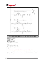
7
4
72
No
Alarms
Description
1
Bypass voltage failure
Bypass voltage is out of the limit
2
Bypass phase sequence wrong
Phase sequence of bypass mains voltage is not OK
3
Inverter not sync. with bypass
Frequency of bypass voltage is beyond the frequency range for online operation or bypass voltage is out of
limit.
4
Battery breaker open
Battery fuses blown or breaker opened by user
5
Battery test failure
Battery failure
6
Rec
tifier t
emperature high
Rec
tifier IGB
T module temperature high
7
Rec
tifier o
verload
RMS current drawn from any of the input lines exceeds its nominal value.
8
Rec
tifier c
ommunication lost
Front panel can not communicate with rec
tifier
9
Input voltage failure
Input voltage is out of the limit
10
Input phase sequence wrong
Phase sequence of input mains voltage is not OK
11
Rec
tifier not sync
. with input
Frequency of input mains voltage is beyond the frequency range of rec
tifier or input mains v
oltage is out of
limit.
12
Rec
tifier not pr
echarged
DC voltage not charged by inrush circuit
13
DC voltage failure
DC Bus voltage is out of the limit
14
Inverter temperature high
Inverter IGBT module temperature high
15
Output overload
RMS current drawn from any of the output lines exceeds its nominal value.
16
Inverter DC component high
Inverter voltage’s DC component is out of the limit
17
Inverter communication lost
Front panel can not communicate with inverter
18
Output DC component high
Output voltage’s DC component is out of the limit
19
Output voltage failure
Output voltage is out of the limit
20
Output short circuit
Short circuit at the output
21
Master communication lost
Slave cannot communicate with master
22
Slave not sync. with master
Slave lost the synchronization with the master
23
N number failure
Parallel UPS count is below the adjusted N number
24
Redundancy lost
Parallel system alarm. The total load is more than the redundancy load.
The formula is: Load % > N / (N+1) * 100
25
Ambient temperature high
Maximal ambient temperature reached
Appendix-1: Alarms List