


Important Notices!
Thank you for choosing LEGRAND UPS System to supply your Critical Application.
This manual contains important information about commissioning, usage and technical properties of the
UPS. It also contains safety information for operator and instructions to secure your critical load. Applying
the recommendation detailed in this manual is necessary to use UPS safely and correctly.
The manufacturer reserves the rights to change the t
echnical specifica
tions
and design without notice.
LEGRAND reserves the rights to change the information in this document
without notice. Refer to
http://ups.legrand.com/
web site to dowload last
release and translations.
Units that are labelled with a CE mark comply with the Standard: EN 62040-1 and EN 62040-2.
Read the manual completely before working on this equipment!
Keep this manual in UPS’s front cover’s pocket for easy consultation!
Reproduction, adaptation, or translation of this manual is prohibited without prior
written permission of LEGRAND Company, except as allowed under the copyright laws.
60
58
UPS output can be switched
off
immediately by Remote Emergency Switching Device interface (ESD)
connection if desired. A remote latched switch can be used as described in abov
e figur
e.
Input
Function
GEN ON
If the GEN ON input is activated by Genset start relay, UPS transfers to Generator Mode,
bypass and battery charging is disabled. Generator icon appears on Energy Flow Diagram
screen.
The factory default setting of Generator contact is “Normally open”.
UPS OFF
If the UPS OFF (ESD) input is set by an ESD switch, UPS stops generating the output voltage
and stops feeding the load. When the voltage on the digital input is removed, you have to
restart UPS.
The factory default setting of ESD contact is “Normally open”.
Table.9
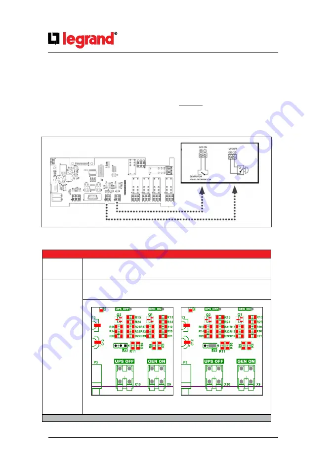
8.3.
Emergency Switching Device and Generator Connections
UPS can be remotely swit
ched off and can be configur
ed for an input supply through genset.
For this purpose, there are two digitals inputs on the Interface card that can activate those functions.
8.2.
Internal SNMP Communication
Internal SNMP card can be installed into SNMP slot placed at the front of UPS. As soon as SNMP installed,
RS232 port would be disabled.
Internal SNMP has the same features as External SNMP; refer to Section 8.1 for more information.
J2: UPS OFF contact NO c
onfigur
ation.
(No jumper)
J2: UPS OFF contact NC c
onfigur
ation.
Figure.8.3-1