background image

Important Notices!

Thank you for choosing LEGRAND UPS System to supply your Critical Application.

This manual contains important information about commissioning, usage and technical properties of the 

UPS. It also contains safety information for operator and instructions to secure your critical load. Applying 

the recommendation detailed in this manual is necessary to use UPS safely and correctly.

The manufacturer reserves the rights to change the t

echnical specifica

tions 

and design without notice.

LEGRAND reserves the rights to change the information in this document 

without notice. Refer to  

http://ups.legrand.com/

 web site to dowload last 

release and translations.

Units that are labelled with a CE mark comply with the Standard:  EN 62040-1 and EN 62040-2. 

Read the manual completely before working on this equipment!

Keep this manual in UPS’s front cover’s pocket for easy consultation!

Reproduction,  adaptation,  or  translation  of  this  manual  is  prohibited  without  prior 

written permission of LEGRAND Company, except as allowed under the copyright laws. 

36

36

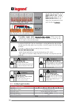
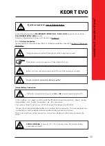
LETHAL  VOLTAGE

of  nominal  720  VDC  is  present  when  the  external  battery 

connections are made.

Read the 

KEOR T EVO Service Manual

 carefully for 

Battery Wiring Diagram in 

External Battery Cabinet!

To  avoid  risk  of  electromagnetic  interference,  separate  the  battery  cables  from 

Input and Output cables.

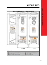
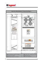
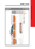
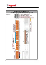
For UPS and External Battery Cabinet Connections, please follow up the instructions below;

• Unplug the cable of Thermal Sensor Board on the UPS. 

• Switch all battery cabinets circuit breaker 

(F5)

 to “

OFF

” position.

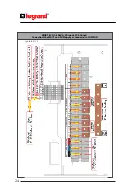
Ground:

 Connect all 

“PB”

 on the battery cabinets directly to

 “PB” 

on the UPS.

• Negative String:

 Connect the

 “-“

 on Battery Cabinet #1 to 

X5 EXT. BATTERY: “-” 

on the UPS. Connect the

 “-“ 

on

Battery

Cabinet #2 to 

X5 EXT. BATTERY: “-”

 on the Battery Cabinet #1 and so on...

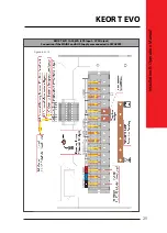
• Positive String:

 Connect the

 “+“

on Battery Cabinet #1 to X5 EXT. BATTERY:

 “+” 

on the UPS. Connect the

 “+“

on 

Battery

Cabinet #2 to 

X5 EXT. BATTERY: “+” 

on the Battery Cabinet #1 and so on...

•  Neutral:

 Connect the 

“N “

on Battery Cabinet #1 to 

X5 EXT. BATTERY: “N” 

on the UPS. Connect the 

“N“

on Battery

Cabinet #2 to 

X5 EXT. BATTERY: “N”

 on the Battery Cabinet #1 and so on...

• External Battery Cabinet Temperature Sensor: Only connect the

 X7: “X7/1 – X7/2 – X7/3” 

on the Battery Cabinet

#1 to X7:

 “X7/1 – X7/2 – X7/3”

 on the UPS. (Not extended 25m length is recommended)

• External Battery Breaker Position Feedback:

For one battery cabinet & UPS c

onfigur

ation: Connect the 

X8: “X8/c – X8/d” 

on the UPS to 

X8: “X8/c –

X8/d” 

on Battery Cabinet #1.

For two battery cabinets & UPS c

onfigur

ation: Connect the 

X8: “X8/c – X8/d”

 on the UPS to 

X8: “X8/c –

X8/e”

 on Battery Cabinet #1. Connect the X8: “X8/d – X8/e” on Battery Cabinet #1 to X8: “X8/c – X8/d” on Battery 

Cabinet #2. 

For three battery cabinets & UPS c

onfigur

ation: Connect the 

X8: “X8/c – X8/d”

 on the UPS to 

X8: “X8/c –

X8/e” 

on Battery Cabinet #1. Connect the 

X8: “X8/d – X8/e” 

on Battery Cabinet #1 to 

X8: “X8/c – X8/e”

 on Battery 

Cabinet #2. Connect the 

X8: “X8/d – X8/e” 

on Battery Cabinet #2 to 

X8: “X8/c – X8/d”

 on Battery Cabinet #3.

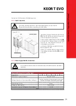
Battery Fast Fuses:

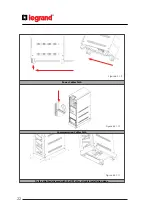
 Mount the battery fast fuses into battery fuse holder on the battery cabinet. (fast fuse indicator 

side must be placed upper side of the holder) Do not close the battery circuit breaker!

External Battery Connection:

KEOR T EVO Battery Cabinet comes with the following cables;
• 3 meters 4 x 16mm² power cables for battery connection 
•  4 meters 2 x 0.5mm² double insulated cables for external battery breaker position feedback signal
• 4 meters 3 x 1.5mm² double insulated cables for external battery cabinet temperature sensor signal
•  3 x Field-mountable Battery Fast Fuses (rating & type depending on the cabinet model)
•  2.9 meters spiral for power cables for protection

If battery cabinets not supplied by LEGRAND, it is the installer’s responsibility to check the 

electrical compatibility and the presence of appropriate protection devices between the 

cabinet and KEOR T EVO.

Summary of Contents for KEOR T EVO 10-60 KVA

Page 1: ...KEOR T EVO 10 60 KVA Installation Operation Manual LE11585AC ...

Page 2: ...bited without prior written permission of LEGRAND Company except as allowed under the copyright laws Important Notices Thank you for choosing LEGRAND UPS System to supply your Critical Application This manual contains important information about commissioning usage and technical properties of the UPS It also contains safety information for operator and instructions to secure your critical load App...

Page 3: ...t followed All packing material must be recycled in compliance with the laws in force in the country where the system is installed Description of the Symbols Used in the Manual UPS Uninterruptible Power Supply ESD Emergency Switching Device RS232 Serial Communication Protocol RS485 Serial Communication Protocol MODBUS Modicon Communication Protocol SNMP Simple Network Management Protocol V Volt A ...

Page 4: ...echnical specifications and design without notice LEGRAND reserves the rights to change the information in this document without notice Refer to http ups legrand com web site to dowload last release and translations Units that are labelled with a CE mark comply with the Standard EN 62040 1 and EN 62040 2 Read the manual completely before working on this equipment Keep this manual in UPS s front co...

Page 5: ...Protocol MODBUS Modicon Communication Protocol SNMP Simple Network Management Protocol V Volt A Ampere P Power For Mains Supply Auxiliary Mains Supply Output Battery Circuit Breaker and Maintenance Bypass Circuit Breaker ON Closing the Circuit OFF Opening the Circuit 1 1 KEOR T EVO Installation Operation Manual 1 FOREWORD 3 1 1 Overview 3 1 2 Manual 3 2 WARRANTY 5 2 1 Terms of Warranty 5 2 2 Out o...

Page 6: ... 8 5 RS485 62 9 OPERATING PROCEDURES FOR SINGLE SYSTEMS 63 9 1 Preparations 63 9 2 Commissioning 64 9 2 1 Start Up UPS with Internal Battery 64 9 2 2 Start Up UPS with External Battery 64 9 3 Decommissioning 65 9 4 Maintenance Bypass Commissioning Instructions 65 Transfer Load Supply from UPS to Internal Maintenance Bypass 9 5 Maintenance Bypass Decommissioning Instructions 66 10 OPERATING PROCEDU...

Page 7: ...type of IT load tertiar best way to reconcile high tech performance and ease of use making user friendly technologically advanced products KEOR T EVO supplies y application lighting or building Furthermore standards deployed by Legrand for R D supplier selection and manufacturing comply with the highest quality standards This product is manufactured in an ISO 9001 ISO14001 certified factory in ful...

Page 8: ...sonnel authorized by the former please refer to the equipment s rating plate data and serial number The manual must be kept for the equipment s useful life cycle and if necessary e g damage which prevents it being consulted even partially the user must ask the Manufacturer for a new copy quoting the publishing code on the cover The manual reflects the state of the art at the moment the equipment w...

Page 9: ...ent manufacturing or installation if it s done by authorized LEGRAND UPS Technical Service Personnel problems during the warranty period the UPS will be repaired spares and labour by the Manufacturer under warranty 2 2 Out of Warranty Terms and Conditions This Warranty does not apply if UPS not commissioned or maintained by an authorized LEGRAND UPS Technical Service staff or an authorized LEGRAND...

Page 10: ... 3 2 Individual Protective Gear There is a high risk of electrical shock with the equipment as well as a considerable short circuit current When installing andservicingtheequipmentitisabsolutely forbiddentoworkwithouttheprotective gearmentionedinthisparagraph The personnel who are going to work with the equipment for installation or maintenance jobs must not wear clothes with baggy sleeves or lace...

Page 11: ...uipment should be used for transportation Never transport in horizontal position The UPS must always stand in a vertical position Make sure that the floor can support the weight of the system Connect the PE ground connector before connecting any other cable UPS is designed for indoor use To reduce the risk of fire or electric shock install this UPS in a temperature and humidity controlled indoor e...

Page 12: ...ontact with skin immediately wash the contaminated skin with water Replaced batteries must be disposed of at authorized battery waste disposal centres A battery can present risk of electric shock and high short circuit currents The following precautions should be observed when working on batteries Remove rings watches necklaces bracelets and all metal objects Only use tools with insulated handles ...

Page 13: ...nearly one This allows perfect adaptation to upstream generator or isolation transformer supply The reactive power consumption decreases During mains voltage failure the energy needed for the load is provided by the internal battery or installed in external battery cabinet s These batteries are charged by an intelligent battery charging circuit when mains voltage is within the limits Batteries are...

Page 14: ...eptable limits and the inverter should be enabled for the UPS to operate in this mode UPS operates in Battery Operation in the following cases While UPS is operating in Online Operation if frequency waveform rms value of mains voltage go beyond the rectifier limits While UPS is operating in Bypass Operation if frequency waveform rms value of mains voltage go beyond Bypass limits If Inverter enable...

Page 15: ...Simple Network Management Protocol V Volt A Ampere P Power For Mains Supply Auxiliary Mains Supply Output Battery Circuit Breaker and Maintenance Bypass Circuit Breaker ON Closing the Circuit OFF Opening the Circuit 11 11 KEOR T EVO Installation Operation Manual 4 3 Bypass Mode UPS transfers the loads automatically to the mains voltage in order to protect them during abnormal conditions While UPS ...

Page 16: ...During Maintenance Bypass operation in case of any mains voltage interruption occurs all loads on the output will be deenergized Maintenance Bypass Operation should not be preferred for long time use 4 7 Operation with External Maintenance Bypass Optional The external manual maintenance bypass may be installed in the general distribution panel where KEOR T EVO is installed or in an external bypass...

Page 17: ... access locations according to EN 60950 1 safety standard which states that the owner should guarantee the following Access to the equipment can only be gained by service persons or by users who have been instructed about the reasons for the restrictions applied to the location and about any precautions that shall be taken and Access is through the use of a tool or lock and key or other means of s...

Page 18: ...and translations Units that are labelled with a CE mark comply with the Standard EN 62040 1 and EN 62040 2 Read the manual completely before working on this equipment Keep this manual in UPS s front cover s pocket for easy consultation Reproduction adaptation or translation of this manual is prohibited without prior written permission of LEGRAND Company except as allowed under the copyright laws 1...

Page 19: ...2 battery life time Room thermal management as specified above is then necessary to avoid battery life time reduction The Battery warranty does not apply if the temperature in the room exceeds 25 C When dual inputs is used Separate Neutral conductor is necessary to be supplied for each input Common Mains Input and Auxiliary Mains Input The two inputs should be supplied by the same MV LV transforme...

Page 20: ...19 28 36 55 73 109 Inverter output current 400V A 15 22 29 44 58 87 Maximum Inverter output current A at 400V 125 overload 10 min 19 28 36 55 73 109 Overload tolerated by the inverter with mains power present kW 10 min 12 5 18 8 25 37 5 50 75 1 min 15 22 5 30 45 60 90 Recommended Protection Devices Rectifier Mains Supply D curve circuit breaker A 3 or 4 pole according neutral system 20 32 40 63 80...

Page 21: ...aws in force in the country where the system is installed Description of the Symbols Used in the Manual UPS Uninterruptible Power Supply ESD Emergency Switching Device RS232 Serial Communication Protocol RS485 Serial Communication Protocol MODBUS Modicon Communication Protocol SNMP Simple Network Management Protocol V Volt A Ampere P Power For Mains Supply Auxiliary Mains Supply Output Battery Cir...

Page 22: ...nt UPS Installation Operating Manual Key for door Battery fuses three pieces Plinths Before the installation please check if your UPS is customized following your special requirements if any 6 1 Models and Dimensions UPS Type Dimension HxWxD mm Net Weight Kg Internal Batteries Type UPS KEOR T EVO 10 KVA 1345H P0 1345 x 400 x 800 122 No battery UPS KEOR T EVO 10 KVA 1345H P1 1345 x 400 x 800 261 60...

Page 23: ... the Circuit KEOR T EVO Installation Operation Manual Description of the Symbols Used in the Manual This symbol points out the instructions which are especially important This symbol points out the risk of electric shock if the following instruction is not followed This symbol points out the instructions which may result with injury of the operator or damage of the equipment if not followed All pa...

Page 24: ...n using the wheels Unscrew the 2 feet to block the UPS in final position It is recommended to store the original UPS packaging for future needs The equipment may only be installed and commissioned by LEGRAND Service staff or authorized distributor skilled person trained and qualified according national safety standards to work on electrical installation with dangerous voltage When the UPS is broug...

Page 25: ...tion is not followed This symbol points out the instructions which may result with injury of the operator or damage of the equipment if not followed All packing material must be recycled in compliance with the laws in force in the country where the system is installed Description of the Symbols Used in the Manual UPS Uninterruptible Power Supply ESD Emergency Switching Device RS232 Serial Communic...

Page 26: ...serves the rights to change the information in this document without notice Refer to http ups legrand com web site to dowload last release and translations Units that are labelled with a CE mark comply with the Standard EN 62040 1 and EN 62040 2 Read the manual completely before working on this equipment Keep this manual in UPS s front cover s pocket for easy consultation Reproduction adaptation o...

Page 27: ...ols Used in the Manual This symbol points out the instructions which are especially important This symbol points out the risk of electric shock if the following instruction is not followed This symbol points out the instructions which may result with injury of the operator or damage of the equipment if not followed All packing material must be recycled in compliance with the laws in force in the c...

Page 28: ...hout notice LEGRAND reserves the rights to change the information in this document without notice Refer to http ups legrand com web site to dowload last release and translations Units that are labelled with a CE mark comply with the Standard EN 62040 1 and EN 62040 2 Read the manual completely before working on this equipment Keep this manual in UPS s front cover s pocket for easy consultation Rep...

Page 29: ...ning the Circuit KEOR T EVO Installation Operation Manual Description of the Symbols Used in the Manual This symbol points out the instructions which are especially important This symbol points out the risk of electric shock if the following instruction is not followed This symbol points out the instructions which may result with injury of the operator or damage of the equipment if not followed Al...

Page 30: ... document without notice Refer to http ups legrand com web site to dowload last release and translations Units that are labelled with a CE mark comply with the Standard EN 62040 1 and EN 62040 2 Read the manual completely before working on this equipment Keep this manual in UPS s front cover s pocket for easy consultation Reproduction adaptation or translation of this manual is prohibited without ...

Page 31: ...ening the Circuit KEOR T EVO Installation Operation Manual Description of the Symbols Used in the Manual This symbol points out the instructions which are especially important This symbol points out the risk of electric shock if the following instruction is not followed This symbol points out the instructions which may result with injury of the operator or damage of the equipment if not followed A...

Page 32: ...out notice LEGRAND reserves the rights to change the information in this document without notice Refer to http ups legrand com web site to dowload last release and translations Units that are labelled with a CE mark comply with the Standard EN 62040 1 and EN 62040 2 Read the manual completely before working on this equipment Keep this manual in UPS s front cover s pocket for easy consultation Repr...

Page 33: ...e Symbols Used in the Manual UPS Uninterruptible Power Supply ESD Emergency Switching Device RS232 Serial Communication Protocol RS485 Serial Communication Protocol MODBUS Modicon Communication Protocol SNMP Simple Network Management Protocol V Volt A Ampere P Power For Mains Supply Auxiliary Mains Supply Output Battery Circuit Breaker and Maintenance Bypass Circuit Breaker ON Closing the Circuit ...

Page 34: ...uts and in stalled upstream According to EN 62040 1 the user should place a warning label on the input distribu tion panel and the other primary power isolators in order to prevent the risk of voltage backfeed This label is supplied with the Installation Manual It indicates RISK OF VOLTAGE BACKFEED Isolate Uninterruptable Power Supply before working on this circuit Then check for Hazardous Voltage...

Page 35: ...evice RS232 Serial Communication Protocol RS485 Serial Communication Protocol MODBUS Modicon Communication Protocol SNMP Simple Network Management Protocol V Volt A Ampere P Power For Mains Supply Auxiliary Mains Supply Output Battery Circuit Breaker and Maintenance Bypass Circuit Breaker ON Closing the Circuit OFF Opening the Circuit 31 31 KEOR T EVO Installation Operation Manual Connect the phas...

Page 36: ...ications and design without notice LEGRAND reserves the rights to change the information in this document without notice Refer to http ups legrand com web site to dowload last release and translations Units that are labelled with a CE mark comply with the Standard EN 62040 1 and EN 62040 2 Read the manual completely before working on this equipment Keep this manual in UPS s front cover s pocket fo...

Page 37: ...sing the Circuit OFF Opening the Circuit KEOR T EVO Installation Operation Manual Description of the Symbols Used in the Manual This symbol points out the instructions which are especially important This symbol points out the risk of electric shock if the following instruction is not followed This symbol points out the instructions which may result with injury of the operator or damage of the equi...

Page 38: ...ications and design without notice LEGRAND reserves the rights to change the information in this document without notice Refer to http ups legrand com web site to dowload last release and translations Units that are labelled with a CE mark comply with the Standard EN 62040 1 and EN 62040 2 Read the manual completely before working on this equipment Keep this manual in UPS s front cover s pocket fo...

Page 39: ...sing the Circuit OFF Opening the Circuit KEOR T EVO Installation Operation Manual Description of the Symbols Used in the Manual This symbol points out the instructions which are especially important This symbol points out the risk of electric shock if the following instruction is not followed This symbol points out the instructions which may result with injury of the operator or damage of the equi...

Page 40: ...sitive String Connect the on Battery Cabinet 1 to X5 EXT BATTERY on the UPS Connect the on Battery Cabinet 2 to X5EXT BATTERY on the Battery Cabinet 1 and so on Neutral Connectthe N onBatteryCabinet 1toX5EXT BATTERY N ontheUPS Connectthe N onBattery Cabinet 2 to X5EXT BATTERY N on the Battery Cabinet 1 and so on External Battery CabinetTemperature Sensor Only connect theX7 X7 1 X7 2 X7 3 on the Ba...

Page 41: ...ed in the Manual This symbol points out the instructions which are especially important This symbol points out the risk of electric shock if the following instruction is not followed This symbol points out the instructions which may result with injury of the operator or damage of the equipment if not followed All packing material must be recycled in compliance with the laws in force in the country...

Page 42: ... information in this document without notice Refer to http ups legrand com web site to dowload last release and translations Units that are labelled with a CE mark comply with the Standard EN 62040 1 and EN 62040 2 Read the manual completely before working on this equipment Keep this manual in UPS s front cover s pocket for easy consultation Reproduction adaptation or translation of this manual is...

Page 43: ...85 Serial Communication Protocol MODBUS Modicon Communication Protocol SNMP Simple Network Management Protocol V Volt A Ampere P Power For Mains Supply Auxiliary Mains Supply Output Battery Circuit Breaker and Maintenance Bypass Circuit Breaker ON Closing the Circuit OFF Opening the Circuit 39 39 KEOR T EVO Installation Operation Manual 10 60kVA External BATTERY Connection 10 60kVA Internal BATTER...

Page 44: ...TEM KEOR T EVO does not modify the neutral system output neutral system is the same as input neutral system Do not connect the output neutral to the protective ground or protective bounding PE or PB Connect the phase cable to X2 OUTPUT X2 L1 X2 L2 X2 L3 terminal and the neutral cable to X2 OUTPUT X2 N terminal Cables must be protected by fuses or MCCB refer to Section 5 4 Electrical Characteristic...

Page 45: ...llowed All packing material must be recycled in compliance with the laws in force in the country where the system is installed Description of the Symbols Used in the Manual UPS Uninterruptible Power Supply ESD Emergency Switching Device RS232 Serial Communication Protocol RS485 Serial Communication Protocol MODBUS Modicon Communication Protocol SNMP Simple Network Management Protocol V Volt A Ampe...

Page 46: ...ions Units that are labelled with a CE mark comply with the Standard EN 62040 1 and EN 62040 2 Read the manual completely before working on this equipment Keep this manual in UPS s front cover s pocket for easy consultation Reproduction adaptation or translation of this manual is prohibited without prior written permission of LEGRAND Company except as allowed under the copyright laws 42 40 Figure ...

Page 47: ...nstructions which may result with injury of the operator or damage of the equipment if not followed All packing material must be recycled in compliance with the laws in force in the country where the system is installed Description of the Symbols Used in the Manual UPS Uninterruptible Power Supply ESD Emergency Switching Device RS232 Serial Communication Protocol RS485 Serial Communication Protoco...

Page 48: ...manual is prohibited without prior written permission of LEGRAND Company except as allowed under the copyright laws 44 42 Figure 6 3 2 1 CANBUS CONNECTION OF TWO PARALLEL UPS CANBUS CONNECTION OF THREE AND MORE PARALLEL UPS Figure 6 3 2 2 6 3 2 Power Connections of Parallel Systems The protection devices must be chosen properly as defined in Section 5 4 considering total parallel UPS power Please ...

Page 49: ...ork Management Protocol V Volt A Ampere P Power For Mains Supply Auxiliary Mains Supply Output Battery Circuit Breaker and Maintenance Bypass Circuit Breaker ON Closing the Circuit OFF Opening the Circuit 45 43 KEOR T EVO Installation Operation Manual 2 Password protected menus for SETTINGS and COMMANDS Figure 7 1 7 1 Front Panel Segments Front panel consists of two segments Colour Touch screen Gr...

Page 50: ...nto DC voltage You may reach the rectifier measurements by touching it Bypass Line Shows that the loads are supplied via Bypass and line colour is Orange If UPS is on Eco Mode it is Green Battery Shows battery conditions If it is discharging the indicator goes down if it is charging the indicator goes up You may reach the battery DC measurements by touching it Inverter Converts DC voltage into AC ...

Page 51: ...the Circuit KEOR T EVO Installation Operation Manual Description of the Symbols Used in the Manual This symbol points out the instructions which are especially important This symbol points out the risk of electric shock if the following instruction is not followed This symbol points out the instructions which may result with injury of the operator or damage of the equipment if not followed All pac...

Page 52: ...translations Units that are labelled with a CE mark comply with the Standard EN 62040 1 and EN 62040 2 Read the manual completely before working on this equipment Keep this manual in UPS s front cover s pocket for easy consultation Reproduction adaptation or translation of this manual is prohibited without prior written permission of LEGRAND Company except as allowed under the copyright laws 48 46...

Page 53: ...the laws in force in the country where the system is installed Description of the Symbols Used in the Manual UPS Uninterruptible Power Supply ESD Emergency Switching Device RS232 Serial Communication Protocol RS485 Serial Communication Protocol MODBUS Modicon Communication Protocol SNMP Simple Network Management Protocol V Volt A Ampere P Power For Mains Supply Auxiliary Mains Supply Output Batter...

Page 54: ...62040 2 Read the manual completely before working on this equipment Keep this manual in UPS s front cover s pocket for easy consultation Reproduction adaptation or translation of this manual is prohibited without prior written permission of LEGRAND Company except as allowed under the copyright laws 50 48 7 2 2 Measurements Menu It provides useful measurements about the UPS and the load You may scr...

Page 55: ...llowed This symbol points out the instructions which may result with injury of the operator or damage of the equipment if not followed All packing material must be recycled in compliance with the laws in force in the country where the system is installed Description of the Symbols Used in the Manual UPS Uninterruptible Power Supply ESD Emergency Switching Device RS232 Serial Communication Protocol...

Page 56: ...omply with the Standard EN 62040 1 and EN 62040 2 Read the manual completely before working on this equipment Keep this manual in UPS s front cover s pocket for easy consultation Reproduction adaptation or translation of this manual is prohibited without prior written permission of LEGRAND Company except as allowed under the copyright laws 52 50 There are 4 different relays and one alarm is assign...

Page 57: ... of electric shock if the following instruction is not followed This symbol points out the instructions which may result with injury of the operator or damage of the equipment if not followed All packing material must be recycled in compliance with the laws in force in the country where the system is installed Description of the Symbols Used in the Manual UPS Uninterruptible Power Supply ESD Emerg...

Page 58: ...eproduction adaptation or translation of this manual is prohibited without prior written permission of LEGRAND Company except as allowed under the copyright laws 54 52 You may choose the language package installed in UPS When you touch the save icon key a confirmation pop up bar will appear You should touch Yes to save the settings Touch No to exit without saving the changes When you touch the sav...

Page 59: ...out the risk of electric shock if the following instruction is not followed This symbol points out the instructions which may result with injury of the operator or damage of the equipment if not followed All packing material must be recycled in compliance with the laws in force in the country where the system is installed Description of the Symbols Used in the Manual UPS Uninterruptible Power Supp...

Page 60: ...62040 1 and EN 62040 2 Read the manual completely before working on this equipment Keep this manual in UPS s front cover s pocket for easy consultation Reproduction adaptation or translation of this manual is prohibited without prior written permission of LEGRAND Company except as allowed under the copyright laws 56 54 7 2 5 About Menu This menu provides information about the UPS itself 7 2 6 Comm...

Page 61: ...ompliance with the laws in force in the country where the system is installed Description of the Symbols Used in the Manual UPS Uninterruptible Power Supply ESD Emergency Switching Device RS232 Serial Communication Protocol RS485 Serial Communication Protocol MODBUS Modicon Communication Protocol SNMP Simple Network Management Protocol V Volt A Ampere P Power For Mains Supply Auxiliary Mains Suppl...

Page 62: ...eep this manual in UPS s front cover s pocket for easy consultation Reproduction adaptation or translation of this manual is prohibited without prior written permission of LEGRAND Company except as allowed under the copyright laws 58 56 8 Communication Interface connectivity cards allow UPS to communicate in a variety of networking environments and with different type of devices Standard and optio...

Page 63: ...th the laws in force in the country where the system is installed Description of the Symbols Used in the Manual UPS Uninterruptible Power Supply ESD Emergency Switching Device RS232 Serial Communication Protocol RS485 Serial Communication Protocol MODBUS Modicon Communication Protocol SNMP Simple Network Management Protocol V Volt A Ampere P Power For Mains Supply Auxiliary Mains Supply Output Bat...

Page 64: ...off immediately by Remote Emergency Switching Device interface ESD connection if desired A remote latched switch can be used as described in above figure Input Function GEN ON If the GEN ON input is activated by Genset start relay UPS transfers to Generator Mode bypass and battery charging is disabled Generator icon appears on Energy Flow Diagram screen The factory default setting of Generator con...

Page 65: ... RS485 Serial Communication Protocol MODBUS Modicon Communication Protocol SNMP Simple Network Management Protocol V Volt A Ampere P Power For Mains Supply Auxiliary Mains Supply Output Battery Circuit Breaker and Maintenance Bypass Circuit Breaker ON Closing the Circuit OFF Opening the Circuit 61 59 KEOR T EVO Installation Operation Manual 8 4 Dry Contacts There are 4 dry contact sockets on the I...

Page 66: ...n Reproduction adaptation or translation of this manual is prohibited without prior written permission of LEGRAND Company except as allowed under the copyright laws 62 60 MODBUS END JUMPER J1 If the UPS is connected at the end of the bus line the jumper should be configured as described The RS485 differential line consists of three pins D is non inverting pin TxD RxD D is inverting pin TxD RxD Mid...

Page 67: ...ol points out the instructions which are especially important This symbol points out the risk of electric shock if the following instruction is not followed This symbol points out the instructions which may result with injury of the operator or damage of the equipment if not followed All packing material must be recycled in compliance with the laws in force in the country where the system is insta...

Page 68: ...ins supply circuit breaker on the UPS Q1 to ON position 6 Switch the inrush circuit breaker on the UPS Q6 to ON position 7 Touch Battery icon to see Battery DC menu measurement Do not close the battery circuit breakers F5 until the difference between DC bus and Battery voltages decreases below 10V 8 Switch the output circuit breaker on the UPS Q2 to ON position 9 Switch the output circuit breaker ...

Page 69: ...et to OFF position 5 Switch the mains supply circuit breaker on the distribution panel to OFF position 6 Switch the auxiliary supply circuit breaker on the distribution panel to OFF position 7 Switch the inrush circuit breaker on the UPS Q6 to OFF position 8 Switch the mains supply circuit breaker on the UPS Q1 to OFF position 9 Switch the auxiliary circuit breaker on the UPS Q4 to OFF position Wa...

Page 70: ...s allowed under the copyright laws 66 64 9 5 Maintenance Bypass Decommissioning Instructions In order to transfer the loads from Maintenance Bypass to UPS without interruption do the following instruction respectively 1 Switch the auxiliary supply circuit breaker on the UPS Q4 to ON position after 30s check if fans are running 2 Switch the mains supply circuit breaker on the UPS Q1 to ON position ...

Page 71: ...tocol SNMP Simple Network Management Protocol V Volt A Ampere P Power For Mains Supply Auxiliary Mains Supply Output Battery Circuit Breaker and Maintenance Bypass Circuit Breaker ON Closing the Circuit OFF Opening the Circuit 67 65 KEOR T EVO Installation Operation Manual 10 Operating Procedures For Parallel Systems 10 1 Introduction KEOR T EVO UPS Systems are designed according to high MTBF figu...

Page 72: ...witch Q6 Inrush circuit breakers of all UPSs to ON position 6 Touch Battery icon to see Battery DC menu measurement Do not close the battery circuit breakers F5 until the difference between DC bus and Battery voltages decreases below 10V 7 If exists switch external Battery circuit breaker to ON position 8 Switch Q2 Output circuit breakers of all UPSs to ON position 9 If exists switch the output ci...

Page 73: ...reakers on the distribution panel to OFF position o unit output switch and OS General Output switch 2 Switch Q2 Output circuit breakers of all Slave to OFF position 3 Switch Q2 Output circuit breaker of Master to OFF position 4 Switch F5 Battery circuit breakers of all Slave to OFF position 5 If exists switch external Battery fuses of all Slave to OFF position 6 Switch F5 Battery circuit breaker o...

Page 74: ...for online operation or auxiliary mains supply voltage is out of limit Check if the auxilary mains supply voltage is in specified limits 11 4 Input phase sequence wrong Alarm It means that phase sequence of common mains supply voltage is not OK Phase sequence of common mains supply input should be changed Please contact the LEGRAND Technical Assistance Center 11 5 Rectifier Not Sync With Input Ala...

Page 75: ...Protocol SNMP Simple Network Management Protocol V Volt A Ampere P Power For Mains Supply Auxiliary Mains Supply Output Battery Circuit Breaker and Maintenance Bypass Circuit Breaker ON Closing the Circuit OFF Opening the Circuit 71 69 KEOR T EVO Installation Operation Manual 11 10 Maintenance Bypass Active Alarm If Maintenance Bypass circuit breaker is brought to ON position this alarm appears Re...

Page 76: ...ry fuses if the battery circuit breaker is closed before DC bus voltage has not reached 360V Please check commissioning procedure in Section 9 Battery fuses should only be replaced with the same rating and type Do not open or mutilate batteries Released electrolyte is harmful to the skin and eyes It may be toxic Batteries should always be replaced by authorized LEGRAND UPS Technical Service Person...

Page 77: ...ts out the instructions which may result with injury of the operator or damage of the equipment if not followed All packing material must be recycled in compliance with the laws in force in the country where the system is installed Description of the Symbols Used in the Manual UPS Uninterruptible Power Supply ESD Emergency Switching Device RS232 Serial Communication Protocol RS485 Serial Communica...

Page 78: ...user 5 Battery test failure Battery failure 6 Rectifier temperature high Rectifier IGBT module temperature high 7 Rectifier overload RMS current drawn from any of the input lines exceeds its nominal value 8 Rectifier communication lost Front panel can not communicate with rectifier 9 Input voltage failure Input voltage is out of the limit 10 Input phase sequence wrong Phase sequence of input mains...

Page 79: ...in compliance with the laws in force in the country where the system is installed Description of the Symbols Used in the Manual UPS Uninterruptible Power Supply ESD Emergency Switching Device RS232 Serial Communication Protocol RS485 Serial Communication Protocol MODBUS Modicon Communication Protocol SNMP Simple Network Management Protocol V Volt A Ampere P Power For Mains Supply Auxiliary Mains S...

Page 80: ... voltage is within the limits 12 Rec sync with Inp Rectifier is synchronized to input frequency 13 Inp ph seq ok Phase sequence of input voltages is OK 14 Rectifier temp ok Rectifier block temperature is within the limits 15 Rectifier load ok RMS current drawn from any of the input lines does not exceed its nominal value 16 DC voltage ok DC bus voltage is within the limits 17 DC voltage ok DC bus ...

Page 81: ...output lines exceeds its nominal value 43 Bypass active UPS is on Bypass Operation 44 Inverter passive Inverter does not operate now 45 Output voltage failure Output voltage is beyond its limits 46 Master com lost This alarm is observed when information flow from master ups is interrupted 47 Input voltage high Input voltage is higher than its limit 48 Input voltage low Input voltage is lower than ...

Page 82: ...3Ph KEOR T EVO 10KVA KEOR T EVO 15KVA KEOR T EVO 20KVA KEOR T EVO 30KVA KEOR T EVO 40KVA KEOR T EVO 60KVA Output Power VA 10 000 15 000 20 000 30 000 40 000 60 000 Nominal Active Power W 10 000 15 000 20 000 30 000 40 000 60 000 Rectifier Input Nominal Voltage 400V Ph Ph 3Ph N PE Input Voltage Range VAC at 50 Load 242 459V Input Voltage Range VAC at full Load with battery charging 15 Frequency Hz ...

Page 83: ...lowed All packing material must be recycled in compliance with the laws in force in the country where the system is installed Description of the Symbols Used in the Manual UPS Uninterruptible Power Supply ESD Emergency Switching Device RS232 Serial Communication Protocol RS485 Serial Communication Protocol MODBUS Modicon Communication Protocol SNMP Simple Network Management Protocol V Volt A Amper...

Page 84: ...unction 06 Write Single Register must be used The data is defined as unsigned words 2 bytes Appendix 5 Modbus List 100 1 L1 Input Voltage R 101 1 L2 Input Voltage R 102 1 L3 Input Voltage R 103 1 L1 Input Current R 104 1 L2 Input Current R 105 1 L3 Input Current R 106 0 1 Input Frequency R 107 1 L1 Output Voltage R 108 1 L2 Output Voltage R 109 1 L3 Output Voltage R 110 1 L1 Output Current R 111 1...

Page 85: ...ce in the country where the system is installed Description of the Symbols Used in the Manual UPS Uninterruptible Power Supply ESD Emergency Switching Device RS232 Serial Communication Protocol RS485 Serial Communication Protocol MODBUS Modicon Communication Protocol SNMP Simple Network Management Protocol V Volt A Ampere P Power For Mains Supply Auxiliary Mains Supply Output Battery Circuit Break...

Page 86: ...on of this manual is prohibited without prior written permission of LEGRAND Company except as allowed under the copyright laws 82 80 Appendix 6 Description of UPS and Block Diagram Name Definition Q1 Common Mains Supply Circuit Breaker Q2 Output Circuit Breaker Q3 Maintenance Bypass Circuit Breaker Q4 Auxiliary Mains Supply Circuit Breaker F5 Battery Fast Fuse Q6 Inrush Circuit Breaker F1 Rectifie...

Page 87: ...r ON Closing the Circuit OFF Opening the Circuit KEOR T EVO Installation Operation Manual Description of the Symbols Used in the Manual This symbol points out the instructions which are especially important This symbol points out the risk of electric shock if the following instruction is not followed This symbol points out the instructions which may result with injury of the operator or damage of ...

Page 88: ...al specifications and design without notice LEGRAND reserves the rights to change the information in this document without notice Refer to http ups legrand com web site to dowload last release and translations Units that are labelled with a CE mark comply with the Standard EN 62040 1 and EN 62040 2 Read the manual completely before working on this equipment Keep this manual in UPS s front cover s ...

Page 89: ...e especially important This symbol points out the risk of electric shock if the following instruction is not followed This symbol points out the instructions which may result with injury of the operator or damage of the equipment if not followed All packing material must be recycled in compliance with the laws in force in the country where the system is installed Description of the Symbols Used in...

Page 90: ...to dowload last release and translations Units that are labelled with a CE mark comply with the Standard EN 62040 1 and EN 62040 2 Read the manual completely before working on this equipment Keep this manual in UPS s front cover s pocket for easy consultation Reproduction adaptation or translation of this manual is prohibited without prior written permission of LEGRAND Company except as allowed un...

Page 91: ...struction is not followed This symbol points out the instructions which may result with injury of the operator or damage of the equipment if not followed All packing material must be recycled in compliance with the laws in force in the country where the system is installed Description of the Symbols Used in the Manual UPS Uninterruptible Power Supply ESD Emergency Switching Device RS232 Serial Com...

Page 92: ... the Standard EN 62040 1 and EN 62040 2 Read the manual completely before working on this equipment Keep this manual in UPS s front cover s pocket for easy consultation Reproduction adaptation or translation of this manual is prohibited without prior written permission of LEGRAND Company except as allowed under the copyright laws 88 86 THREE PARALLEL UNITS N 1 Redundant Configuration with Single D...

Page 93: ......

Page 94: ...ervice BP 30076 87002 LIMOGES CEDEX FRANCE www legrand com Legrand reserves at any time the right to modify the contents of this booklet and to communicate in any form and modality the changes brought to the same Installer stamp ...

Reviews: