


KEOR T EVO
Installa
tion & Oper
ation M
anual
Description of the Symbols Used in the Manual
This symbol points out the instructions which are especially important.
This symbol points out the risk of electric shock if the following instruction is
not followed.
This symbol points out the instructions, which may result with injury of the
operator or damage of the equipment if not followed.
All packing material must be recycled in compliance with the laws in force in the
country where the system is installed.
Description of the Symbols Used in the Manual
UPS: Uninterruptible Power Supply
ESD: Emergency Switching Device
RS232: Serial Communication Protocol
RS485: Serial Communication Protocol
MODBUS: Modicon Communication Protocol
SNMP: Simple Network Management Protocol
V: Volt
A: Ampere
P: Power
For Mains Supply, Auxiliary Mains Supply, Output, Battery Circuit Breaker and Maintenance Bypass Circuit
Breaker;
“ON”: Closing the Circuit
“OFF”: Opening the Circuit
39
39
KEOR T EVO
Installa
tion & Oper
ation M
anual
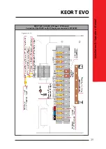
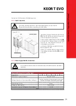
10-60kVA External BATTERY Connection
10-60kVA Internal BATTERY Connection
10-30kVA Model 0 Battery Selection Terminal
40-60kVA Model 0 Battery Selection Terminal
6.3.1.5.
Battery Connection Configurations for Model 0
Figure.6.3.1.5-2
Figure.6.3.1.5-3
Figure.6.3.1.5-4
Figure.6.3.1.5-1
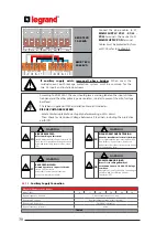
Do not use internal and external battery together!
Set the external battery configuration according to the instructions below.
1. Unscrew the battery selection terminal insulator.
2. Unscrew the cables which are on the upper side of the battery selection terminal.
3. Unscrew the external battery cables which is on the bottom side of the battery selection terminal.
4.
5.
Connect the cables which are come from fuse holder with external battery cables to bottom side of
the battery selection terminal as shown in Figure 6.3.1.5-2.
Remove the internal battery cables from the UPS cabinet as shown in Figure 6.3.1.5-2.
6. Screw the battery selection terminal insulator.
Battery connection configuration can be adjusted as internal or external battery by changing cabling of
battery selection terminal.
As can be seen in Figure 6.3.1.5-1, battery selection terminal is adjusted to internal battery as the factory
setting. If the battery configuration is desired to be used as an external battery, the cabling of battery
selection terminal have to adjust as shown in Figure 6.3.1.5-2.
If external battery
cabinet used
, remove the flying cables that are not connected in
the batter
y compartment.