


Important Notices!
Thank you for choosing LEGRAND UPS System to supply your Critical Application.
This manual contains important information about commissioning, usage and technical properties of the
UPS. It also contains safety information for operator and instructions to secure your critical load. Applying
the recommendation detailed in this manual is necessary to use UPS safely and correctly.
The manufacturer reserves the rights to change the t
echnical specifica
tions
and design without notice.
LEGRAND reserves the rights to change the information in this document
without notice. Refer to
http://ups.legrand.com/
web site to dowload last
release and translations.
Units that are labelled with a CE mark comply with the Standard: EN 62040-1 and EN 62040-2.
Read the manual completely before working on this equipment!
Keep this manual in UPS’s front cover’s pocket for easy consultation!
Reproduction, adaptation, or translation of this manual is prohibited without prior
written permission of LEGRAND Company, except as allowed under the copyright laws.
16
16
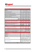
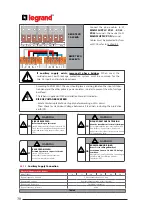
Installation Parameters
Model (kVA)
10
15
20
30
40
60
Phase in/out
3Ph+N+PE / 3Ph+N+PB
Rated output apparent power (kVA)
10
15
20
30
40
60
Rated output active power (kW)
10
15
20
30
40
60
Rated input current (A) at 400V nominal input voltage
15
23
31
46
61
92
Maximum input current (A) at 340V input v full load + battery charging
18
27
36
54
72
108
Rated bypass current (A) at 400V nominal input voltage
15
22
29
44
58
87
Maximum bypass current (A) at 400V, 125% overload 10 min
19
28
36
55
73
109
Inverter output current @ 400V (A)
15
22
29
44
58
87
Maximum Inverter output current (A) at 400V, 125% overload 10 min
19
28
36
55
73
109
Overload tolerated by the inverter (with mains power present) (kW)
10 min
12.5
18.8
25
37.5
50
75
1 min
15
22.5
30
45
60
90
Recommended Protection Devices - Rec
tifier/M
ains Supply -*
D curve circuit breaker (A) (3 or 4-pole according neutral system)
20
32
40
63
80
125
GG fuse (A)
20
32
40
63
80
125
Recommended Protection Devices – General Bypass/Auxiliary Mains Supply –*
D curve circuit breaker (A) (3 or 4 poles according neutral system)
20
32
40
63
80
100
Maximum I2t supported by the bypass (A2s) (10ms)
6700
11200
15000
25300
Icc max (A)
1200
1500
1700
2300
Protection Devices – Battery Fast Fuse –
Ferrule style high speed fuses and with indicating striker
(High Speed FWP Bussmann Fuse 22x58mm 690VAC (IEC)) (A)
25
32
50
63
80
100
Output max recommended Protection Devices to assure discrimination in battery mode operation
C curve circuit breaker (A) (3-pole) **(3 or 4 poles according neutral system)
≤3
≤4
≤6
≤10
≤13
B curve circuit breaker (A) (3-pole) (3 or 4 poles according neutral system)
≤6
≤8
≤13
≤20
≤25
Maximum inverter short circuit current for 50 ms: IK1=IK2=IK3 =IF
2.1xIn
Max. Cable Cross-Section for Terminals**
Rec
tifier (mm²)
35
General Bypass (mm²)
35
Battery (mm²)
16
35
Output (mm²)
Neutral (mm²)
35
Protective Earth/Bonding
Recommended cross section for ground wire
at least half of the section of cable phases AND
shall comply with the standards of the country
(for example NFC 15100 in France).
Leakage Current Protection ***
Minimum 300 mA delayed (Type-B). When used,
the residual current earth leakage protection
system must be common for the two AC inputs
(common & auxiliary mains) and installed
upstream.
Table.2
35
16
16
16
16