


70
INDICATION
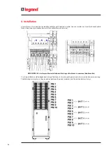
1 KB (Battery Kit) represents a string of 48 batteries in series.
In case of models with internal battery drawers, 1 KB is made up of 2 drawers.
8. Set the correct battery capacity in Ah of the single KB in the tab “System”
INDICATION
The UPS calculates the total battery capacity as produced by the total KB * Capacity.
9. Provide the mains supply to the UPS by closing the external mains input/bypass input disconnectors (ON position).
10. Tap on the tab “System” and select ON on the item “System Power” to turn ON the UPS. Ensure that the EPO is connect-
ed to the SSS interface (the default setting is NC).
11. The LEDs on the power modules turn to steady yellow while they are powered from the batteries. When they are
powered from the mains and the UPS is on-line, the LEDs turn to steady green.
12. Check that the output voltage and frequency values set correspond with the requirements of the load. If not, turn off
the UPS and set the correct values (see step 6).
13. Provide the power supply to the load by closing the external output disconnector (ON position).
14. Close the UPS door and remove the key.
DANGER
Do not remove the power modules during the functioning of the UPS without activating the hot-swap procedure (de-
scribed in paragraph 6.3.1). The removal of one or more power modules without the proper use of the hot-swap proce-
dure could damage the equipment.
CAUTION
The keys to open the UPS door and the installation manual must not be left at the disposal of the operator.
5.3
Switching off the UPS
Follow this procedure in case there is the need to turn off the UPS:
1. Tap on the Setting icon of the menu bar at the bottom of the display.
2. Tap on the tab “System” and select OFF on the item “System Power” to turn OFF the UPS.
3. The LEDs on the power modules turn to steady blue when they are in stand-by mode and the UPS is no longer sup-
plying the load.
DANGER
In this stand-by condition there are still hazardous voltages on the UPS.
To disconnect the UPS from all sources of supply:
- open the external mains input/bypass input disconnectors (ON position);
- open all the fuse breakers of the external battery cabinets (if present);
- remove at least one battery drawer for every shelf present to interrupt the battery string.
5. Configuration and start-up
Summary of Contents for Keor MOD 100
Page 1: ...Part LE11406AB 04 19 01 GF Keor MOD Installation and maintenance manual ...
Page 2: ...2 EN ENGLISH 3 Keor MOD ...
Page 20: ...20 4 Installation 3 4 5 ...
Page 22: ...22 4 Installation 9 10 ...
Page 24: ...24 4 Installation KEOR MOD 250 earthing bars ...
Page 79: ...Keor MOD Installation and maintenance manual 79 6 3 3 Removal of the SSS drawer 1 2 3 4 ...
Page 87: ...Keor MOD Installation and maintenance manual 87 ...
Page 88: ...88 9 Mechanical characteristics ...
Page 89: ...Keor MOD Installation and maintenance manual 89 ...
Page 90: ...90 9 Mechanical characteristics ...
Page 92: ...92 9 Mechanical characteristics 9 3 Battery drawer all the dimensions are in mm ...