


Keor MOD
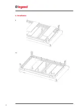
Installa
tion and main
tenanc
e manual
35
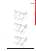
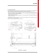
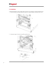
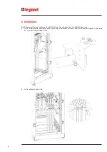
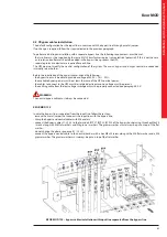
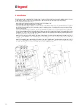
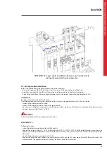
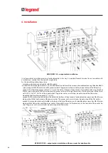
4.2.6 Input cables installation
The default configuration has the input line in common with the bypass line through a metal jumper.
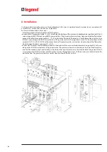
Before the installation of the input cables, check the following:
- the mains line must be able to provide an input voltage of 400 V + 15% - 20%;
- the available mains power must be at least the same of the UPS nominal power;
- the cables to connect to the UPS must be isolated upstream and no voltage must be present;
- the earthing cable from the low voltage switchgear must be properly connected (see paragraph 4.2.3).
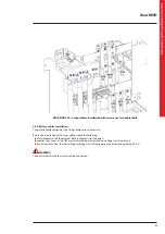
WARNING
The neutral input cable must always be connected.
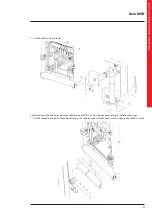
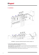
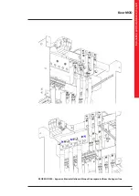
KEOR MOD 125
The default configuration has the input line in common with the bypass line through a metal jumper.
If no change is required, follow these steps:
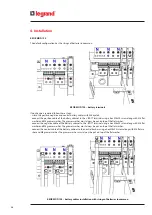
- unscrew the three hex M8x25 screws that fix the jumper to the bypass terminal of the busbar;
- crimp the input and neutral cables with M8 eyelets;
- connect the input cables L1, L2, L3 to the metal jumper of the terminals BYP L1, BYP L2, BYP L3 of the bypass busbar
using the three screws removed previously along with M8 flat washers and M8 grower washers. The grower washer must
always be put on top of the flat washer;
- do not change the phase sequence (L1, L2, L3);
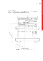
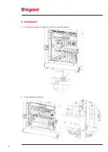
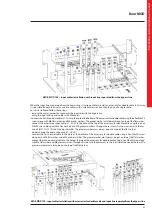
- connect the input neutral cable to the neutral busbar with a hex M8x20 screw along with a M8 flat washer and a M8
grower washer. The grower washer must always be put on top of the flat washer.
Summary of Contents for Keor MOD 100
Page 1: ...Part LE11406AB 04 19 01 GF Keor MOD Installation and maintenance manual ...
Page 2: ...2 EN ENGLISH 3 Keor MOD ...
Page 20: ...20 4 Installation 3 4 5 ...
Page 22: ...22 4 Installation 9 10 ...
Page 24: ...24 4 Installation KEOR MOD 250 earthing bars ...
Page 79: ...Keor MOD Installation and maintenance manual 79 6 3 3 Removal of the SSS drawer 1 2 3 4 ...
Page 87: ...Keor MOD Installation and maintenance manual 87 ...
Page 88: ...88 9 Mechanical characteristics ...
Page 89: ...Keor MOD Installation and maintenance manual 89 ...
Page 90: ...90 9 Mechanical characteristics ...
Page 92: ...92 9 Mechanical characteristics 9 3 Battery drawer all the dimensions are in mm ...