


Keor MOD
Installa
tion and main
tenanc
e manual
67
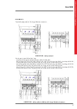
4.5.1 Emergency Power Off (EPO)
The UPS has a contact that can be used to activate the immediate stop of the equipment. It can be set as normally closed
(NC) or normally open (NO) from the user interface. The default configuration is NC.
The EPO terminal is found on pins 1 and 2 of contact N13 of the SSS interface.
Use a voltage-free contact to connect the epo externally.
INDICATION
It is not possible to connect in parallel the EPO circuits of several UPS. If necessary, use contacts on the EPO emergency
pushbutton isolated from each other.
The electric characteristics of the EPO interface are:
- voltage between terminals 1 and 2 of contact N13 with open circuit: 5 Vdc
- current between terminals 1and 2 of contact N13 with closed circuit: 5 mA
Summary of Contents for Keor MOD 100
Page 1: ...Part LE11406AB 04 19 01 GF Keor MOD Installation and maintenance manual ...
Page 2: ...2 EN ENGLISH 3 Keor MOD ...
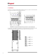
Page 20: ...20 4 Installation 3 4 5 ...
Page 22: ...22 4 Installation 9 10 ...
Page 24: ...24 4 Installation KEOR MOD 250 earthing bars ...
Page 79: ...Keor MOD Installation and maintenance manual 79 6 3 3 Removal of the SSS drawer 1 2 3 4 ...
Page 87: ...Keor MOD Installation and maintenance manual 87 ...
Page 88: ...88 9 Mechanical characteristics ...
Page 89: ...Keor MOD Installation and maintenance manual 89 ...
Page 90: ...90 9 Mechanical characteristics ...
Page 92: ...92 9 Mechanical characteristics 9 3 Battery drawer all the dimensions are in mm ...