


26
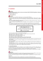
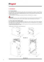
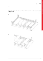
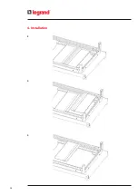
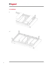
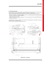
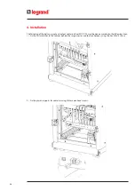
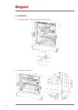
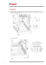
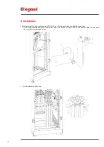
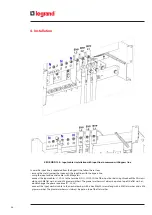
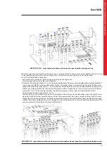
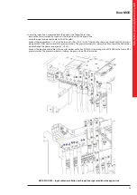
4. Installation
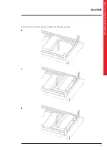
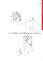
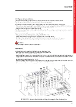
The fastening of the battery, input and output cables on Keor MOD 125 must be done according to the following steps:
1) Fix the first metal bar to the cabinet, behind the surge arrester and the fuse holders, using two hex M8x14 screws.
2) Fix the plastic supports for cable ties using M6 torx pan head screws.
Summary of Contents for Keor MOD 100
Page 1: ...Part LE11406AB 04 19 01 GF Keor MOD Installation and maintenance manual ...
Page 2: ...2 EN ENGLISH 3 Keor MOD ...
Page 20: ...20 4 Installation 3 4 5 ...
Page 22: ...22 4 Installation 9 10 ...
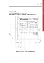
Page 24: ...24 4 Installation KEOR MOD 250 earthing bars ...
Page 79: ...Keor MOD Installation and maintenance manual 79 6 3 3 Removal of the SSS drawer 1 2 3 4 ...
Page 87: ...Keor MOD Installation and maintenance manual 87 ...
Page 88: ...88 9 Mechanical characteristics ...
Page 89: ...Keor MOD Installation and maintenance manual 89 ...
Page 90: ...90 9 Mechanical characteristics ...
Page 92: ...92 9 Mechanical characteristics 9 3 Battery drawer all the dimensions are in mm ...