


66
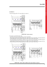
4.5
SSS interface
TERMINAL
PINS
FUNCTION
Analogic
floating
inputs
N16
1-2
CONFIGURABLE CONTACT 3
Maximum input voltage: 15V
15 kΩ pull-up
3-4
CONFIGURABLE CONTACT 4
N15
1-2
CONFIGURABLE CONTACT 1
3-4
CONFIGURABLE CONTACT 2
N14
1-2
EXTERNAL MAINTENANCE
BYPASS SWITCH
3-4
EXTERNAL TEMPERATURE
Maximum Input Voltage: 5V
(not available at the moment)
Digital
floating
inputs
N13
1-2
EPO
Maximum input voltage: 5V
1 kΩ pull-up
3-4
EXTERNAL OUTPUT SWITCH
N12
1-2
GENSET
It allows the UPS to know if
there is an external generator.
If the contact is closed, the
generator is present.
3-4
EXTERNAL BATTERY SWITCH
Output
contacts
N11
4-5-6
CONFIGURABLE CONTACT 3
NC/NO contacts
30 Vdc -1 A
125 Vac - 0,5 A (resistive load).
1-2-3
CONFIGURABLE CONTACT 2
N10
4-5-6
CONFIGURABLE CONTACT 1
1-2-3
BYPASS STATUS
N9
4-5-6
ALARM
1-2-3
OVERLOAD
N8
4-5-6
BATTERY AUTONOMY RESERVE
1-2-3
MAINS/BATTERY STATUS
N6
1-2
AUXILIARY REMOTE BYPASS
CONTACT
It is possible to enable the forced
bypass mode through this NO contact
CONNECTOR
TERMINAL
N3B
USB HOST
Port used for FW updates
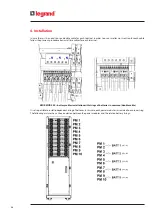
4. Installation
Summary of Contents for Keor MOD 100
Page 1: ...Part LE11406AB 04 19 01 GF Keor MOD Installation and maintenance manual ...
Page 2: ...2 EN ENGLISH 3 Keor MOD ...
Page 20: ...20 4 Installation 3 4 5 ...
Page 22: ...22 4 Installation 9 10 ...
Page 24: ...24 4 Installation KEOR MOD 250 earthing bars ...
Page 79: ...Keor MOD Installation and maintenance manual 79 6 3 3 Removal of the SSS drawer 1 2 3 4 ...
Page 87: ...Keor MOD Installation and maintenance manual 87 ...
Page 88: ...88 9 Mechanical characteristics ...
Page 89: ...Keor MOD Installation and maintenance manual 89 ...
Page 90: ...90 9 Mechanical characteristics ...
Page 92: ...92 9 Mechanical characteristics 9 3 Battery drawer all the dimensions are in mm ...