Operator's Manual
Pass/Fail Testing
Pass/Fail testing is a type of mask testing that is particularly useful for comparing newly acquired
signals to a previously acquired "golden standard" waveform.
A mask defines an area of the grid against which a source Channel, Zoom, or Math trace is compared.
Test conditions are associated with the mask, defining how the waveform is to be compared to the
masked area (e.g., some/all values fall within, some/all values fall outside), and a Pass or Fail result is
returned indicating the condition was found to be true or false.
Pass/Fail testing can be done using a pre-defined mask or a mask created from your actual waveform,
with vertical and horizontal tolerances that you define. Some industry standard masks used for
compliance testing are included with the oscilloscope software. The mask test can be confined to just a
portion of the trace by the use of a measure gate.
Access Pass/Fail Test Dialogs
1. Choose
Analysis
→
Pass/Fail
to display the
Pass/Fail
dialog.
2. Touch the
Q
x
button
or tab where you want to set up the mask.
The source waveform will be tested against this mask whenever Q
x
is enabled on the Pass/Fail
dialog.
3. From the pop-up menu, select
Pass/Fail Condition
and
Mask test.
.
The Qx dialog opens with the Mask test condition selected and the
Test
,
Load Mask
,
Make Mask
, and
Gate
right-hand dialogs displayed. On these dialogs, you manage, make, and apply gates to your
mask.
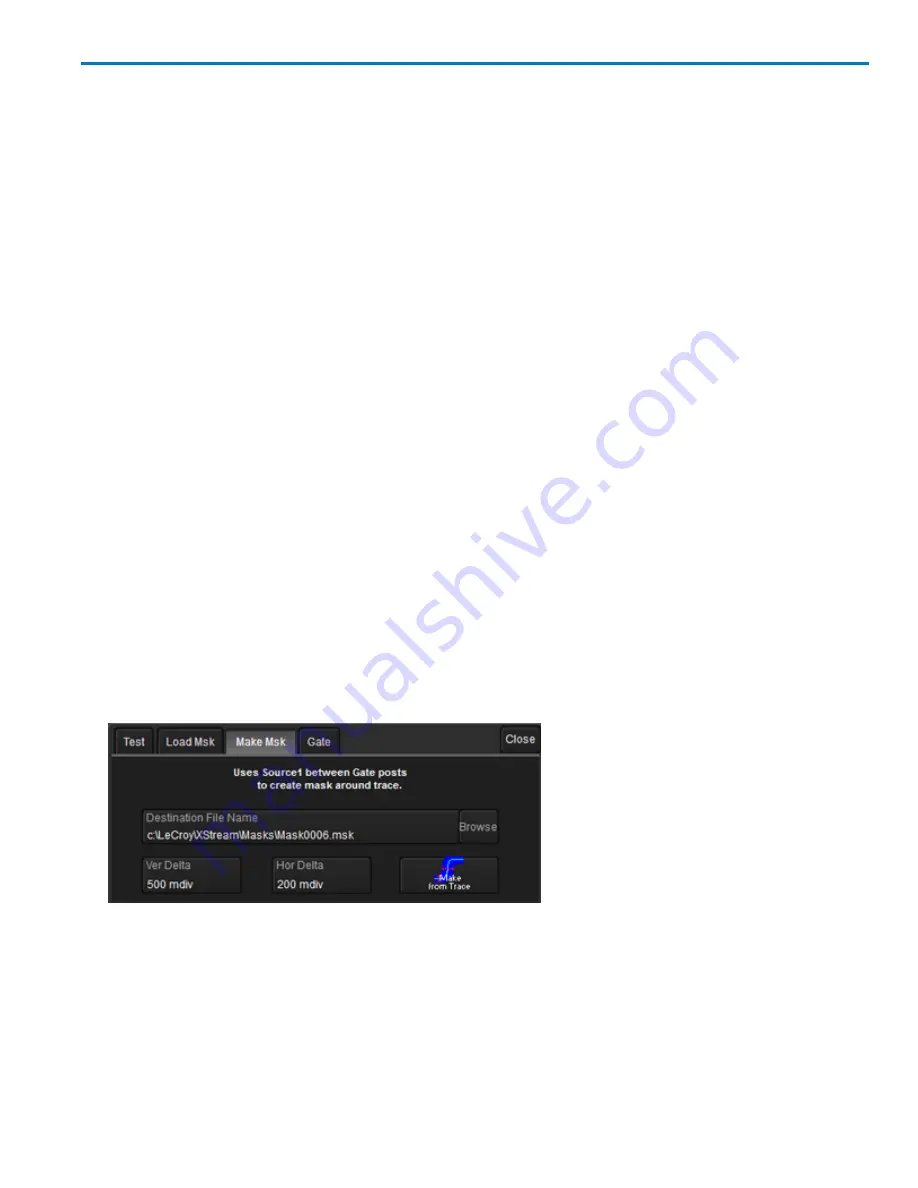
Make Mask
Use this procedure to create a new mask based on a source waveform. The mask will cover the area of
the waveform, plus the boundary values you enter.
1. Touch the
Make Mask tab
to display the dialog.
2. If desired, enter a new
Destination File Name
and path, or touch Browse and select a previous file to
overwrite. The file name should end with the
.msk
extension.
3. Touch the
Ver Delta
and
Hor Delta
fields and enter boundary values using the pop-up numeric keypad
or the Front Panel Adjust knob.
4. Touch
Make from Trace
.
922499 Rev B
93