EM522-CAN Field bus Stepper Drive User Manual V1.0
6
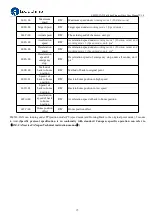
3.3 LED Light Indication
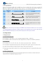
There are two LED lights for DM56-CAN. The GREEN one is the power indicator which will be always on generally. The
RED one is a protection indicator which will flash 1-2 times in a 3-second period, when protection enabled for a
EM522-CAN. Different number of flashes indicates different protection type ,as shown following table.
Priority
Time(s) of
Blink
Sequence wave of red LED
Description
1st
1
Over-current protection activated when peak
current exceeds the limit.
2nd
2
Over-voltage protection activated when drive
working voltage is greater than 90VDC
3rd
8
EEPROM Fault(need to configure parameter )
4th
12
Operational Amplifier Fault (need to configure
parameter )
!
Notice
Notes:
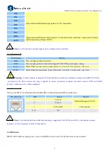
(1) The protections for detecting
.fault of EEPROM fault and Operational Amplifier need to turn on manually
via configuring parameter, read section 4.4 for detail; (2) When one of the protection is active, the motor shaft will be free
and the red LED blinks. Restart the power to make it function properly after removing above problems.
4. Getting Started
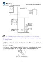
4.1 Wiring Instruction
4.1.1 Power supply & motor cable
Wire diameter: +VDC, GND, A+, A-, B+, B- terminal wire diameter≥0.3mm
2
(AWG15-22)
Recommend to connect a noise filter between power supply and drive, can improve anti-interference performance.
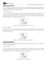
4.1.2 I/O signal cable
Wire diameter: IN1+, IN1-, IN2+, IN2-, IN3+, IN3- terminal wire diameter≥0.12mm
2
(AWG24-26)
Recommended to adopt shielded twisted pair cable, cable length as short as possible, suggest no more than 3 meters
Wiring: As far as possible away from the power line wiring, in order to prevent interference
Please connect surge absorber to inductive device, such as anti-parallel diode for DC coil, parallel RC-snubbers circuit
for AC coil.
4.1.3 CAN communication cable
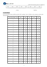
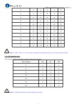
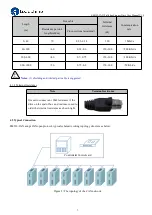
There are coupling relationship between CAN bus cable length, guide line cross sectional area, terminal resistance and
communication rate, recommended combinations as below:


